


–ù–∞–ª–∏—á–∏–µ: –ü–æ –∑–∞–ø—Ä–æ—Å—É–ü–æ –∑–∞–ø—Ä–æ—Å—É –ü–æ –∑–∞–ø—Ä–æ—Å—É –ü–æ –∑–∞–ø—Ä–æ—Å—É

–ê–º–µ—Ä–∏–∫–∞–Ω—Å–∫–∞—è –∫–æ–º–ø–∞–Ω–∏—è Keysight Technologies –Ω–∞—á–∞–ª–∞ —Å–≤–æ—é –∏—Å—Ç–æ—Ä–∏—é –≤ 1930-—Ö –≥–æ–¥–∞—Ö –ø—Ä–æ—à–ª–æ–≥–æ –≤–µ–∫–∞. –°–µ–≥–æ–¥–Ω—è ‚Äì —ç—Ç–æ –ª–∏–¥–µ—Ä –≤ –ø—Ä–æ–∏–∑–≤–æ–¥—Å—Ç–≤–µ –∏–∑–º–µ—Ä–∏—Ç–µ–ª—å–Ω–æ–≥–æ –æ–±–æ—Ä—É–¥–æ–≤–∞–Ω–∏—è –∏ –°–ê–ü–Ý (—Å–∏—Å—Ç–µ–º –∞–≤—Ç–æ–º–∞—Ç–∏–∑–∏—Ä–æ–≤–∞–Ω–Ω–æ–≥–æ –ø—Ä–æ–µ–∫—Ç–∏—Ä–æ–≤–∞–Ω–∏—è). Keysight Technologies –ø—Ä–µ–¥–ª–∞–≥–∞–µ—Ç –∏–Ω—Ç–µ–≥—Ä–∏—Ä–æ–≤–∞–Ω–Ω—ã–µ —Ä–µ—à–µ–Ω–∏—è, –æ–±—ä–µ–¥–∏–Ω—è—é—â–∏–µ –∏–∑–º–µ—Ä–µ–Ω–∏—è, —ç–∫—Å—Ç—Ä–∞–∫—Ü–∏—é –ø–∞—Ä–∞–º–µ—Ç—Ä–æ–≤ –∏ –≤–µ—Ä–∏—Ñ–∏–∫–∞—Ü–∏—é —Ä–∞–∑—Ä–∞–±–æ—Ç–æ–∫.
Компания Keysight Technologies производит осциллографы, анализаторы, измерители, генераторы, источники питания, а также… подробнее
–ö–ª—é—á–µ–≤—ã–µ –≤–æ–∑–º–æ–∂–Ω–æ—Å—Ç–∏ –∏ —Ç–µ—Ö–Ω–∏—á–µ—Å–∫–∏–µ —Ö–∞—Ä–∞–∫—Ç–µ—Ä–∏—Å—Ç–∏–∫–∏
–û–ø–∏—Å–∞–Ω–∏–µ
 –£—Ç–≤–µ—Ä–∂–¥–µ–Ω–Ω—ã–π —Ç–∏–ø —Å—Ä–µ–¥—Å—Ç–≤ –∏–∑–º–µ—Ä–µ–Ω–∏–π.
–í–Ω–µ—Å–µ–Ω –≤ –ì–æ—Å—É–¥–∞—Ä—Å—Ç–≤–µ–Ω–Ω—ã–π —Ä–µ–µ—Å—Ç—Ä —Å—Ä–µ–¥—Å—Ç–≤ –∏–∑–º–µ—Ä–µ–Ω–∏–π –∑–∞ –Ω–æ–º–µ—Ä–æ–º 51077-12.
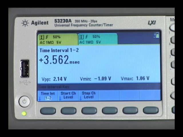
–û–¥–Ω–æ–∫–∞–Ω–∞–ª—å–Ω—ã–π –í–ß —á–∞—Å—Ç–æ—Ç–æ–º–µ—Ä Keysight 53210A —Å –¥–∏–∞–ø–∞–∑–æ–Ω–æ–º —á–∞—Å—Ç–æ—Ç 350 –ú–ì—Ü –æ–±–µ—Å–ø–µ—á–∏–≤–∞–µ—Ç –±—ã—Å—Ç—Ä–æ–µ –∏ —Ç–æ—á–Ω–æ–µ –∏–∑–º–µ—Ä–µ–Ω–∏–µ —á–∞—Å—Ç–æ—Ç—ã –∏ –∏–º–µ–µ—Ç –ø—Ä–æ—Å—Ç–æ–π —É–¥–æ–±–Ω—ã–π –ø–æ–ª—å–∑–æ–≤–∞—Ç–µ–ª—å—Å–∫–∏–π –∏–Ω—Ç–µ—Ä—Ñ–µ–π—Å. –î–ª—è –∏–∑–º–µ—Ä–µ–Ω–∏—è —á–∞—Å—Ç–æ—Ç—ã –≤ –¥–∏–∞–ø–∞–∑–æ–Ω–µ –¥–æ 6 –ì–ì—Ü –∏–ª–∏ –¥–æ 15 –ì–ì—Ü –º–æ–∂–µ—Ç –±—ã—Ç—å –¥–æ–±–∞–≤–ª–µ–Ω –¥–æ–ø–æ–ª–Ω–∏—Ç–µ–ª—å–Ω—ã–π –°–í–ß –∫–∞–Ω–∞–ª.

–ö–ª—é—á–µ–≤—ã–µ –≤–æ–∑–º–æ–∂–Ω–æ—Å—Ç–∏ –∏ —Ç–µ—Ö–Ω–∏—á–µ—Å–∫–∏–µ —Ö–∞—Ä–∞–∫—Ç–µ—Ä–∏—Å—Ç–∏–∫–∏
–û–ø–∏—Å–∞–Ω–∏–µ
–£—Ç–≤–µ—Ä–∂–¥–µ–Ω–Ω—ã–π —Ç–∏–ø —Å—Ä–µ–¥—Å—Ç–≤ –∏–∑–º–µ—Ä–µ–Ω–∏–π.
–í–Ω–µ—Å–µ–Ω –≤ –ì–æ—Å—É–¥–∞—Ä—Å—Ç–≤–µ–Ω–Ω—ã–π —Ä–µ–µ—Å—Ç—Ä —Å—Ä–µ–¥—Å—Ç–≤ –∏–∑–º–µ—Ä–µ–Ω–∏–π –∑–∞ –Ω–æ–º–µ—Ä–æ–º 51077-12.
–û–¥–Ω–æ–∫–∞–Ω–∞–ª—å–Ω—ã–π –í–ß —á–∞—Å—Ç–æ—Ç–æ–º–µ—Ä Keysight 53210A —Å –¥–∏–∞–ø–∞–∑–æ–Ω–æ–º —á–∞—Å—Ç–æ—Ç 350 –ú–ì—Ü –æ–±–µ—Å–ø–µ—á–∏–≤–∞–µ—Ç –±—ã—Å—Ç—Ä–æ–µ –∏ —Ç–æ—á–Ω–æ–µ –∏–∑–º–µ—Ä–µ–Ω–∏–µ —á–∞—Å—Ç–æ—Ç—ã –∏ –∏–º–µ–µ—Ç –ø—Ä–æ—Å—Ç–æ–π —É–¥–æ–±–Ω—ã–π –ø–æ–ª—å–∑–æ–≤–∞—Ç–µ–ª—å—Å–∫–∏–π –∏–Ω—Ç–µ—Ä—Ñ–µ–π—Å. –î–ª—è –∏–∑–º–µ—Ä–µ–Ω–∏—è —á–∞—Å—Ç–æ—Ç—ã –≤ –¥–∏–∞–ø–∞–∑–æ–Ω–µ –¥–æ 6 –ì–ì—Ü –∏–ª–∏ –¥–æ 15 –ì–ì—Ü –º–æ–∂–µ—Ç –±—ã—Ç—å –¥–æ–±–∞–≤–ª–µ–Ω –¥–æ–ø–æ–ª–Ω–∏—Ç–µ–ª—å–Ω—ã–π –°–í–ß –∫–∞–Ω–∞–ª.
|
–ù–æ–º–µ—Ä –≤ –ì–æ—Å—Ä–µ–µ—Å—Ç—Ä–µ |
–ù–∞–∏–º–µ–Ω–æ–≤–∞–Ω–∏–µ –°–ò |
–û–±–æ–∑–Ω–∞—á–µ–Ω–∏–µ —Ç–∏–ø–∞ –°–ò |
–ò–∑–≥–æ—Ç–æ–≤–∏—Ç–µ–ª—å |
–°—Ä–æ–∫ —Å–≤–∏–¥–µ—Ç–µ–ª—å—Å—Ç–≤–∞ –∏–ª–∏ –∑–∞–≤–æ–¥—Å–∫–æ–π –Ω–æ–º–µ—Ä |
|---|---|---|---|---|
|
51077-12 |
–ß–∞—Å—Ç–æ—Ç–æ–º–µ—Ä—ã |
53210–ê, 53220–ê, 53230–ê |
–§–∏—Ä–º–∞ "Agilent Technologies", –ú–∞–ª–∞–π–∑–∏—è |
11.09.2017 |
|
51077-12 |
–ß–∞—Å—Ç–æ—Ç–æ–º–µ—Ä—ã |
53210–ê, 53220–ê, 53230–ê |
–§–∏—Ä–º–∞ "Keysight Technologies Microwave Products (M) Sdn. Bhd.", –ú–∞–ª–∞–π–∑–∏—è |
17.08.2022 |
|
–ù–æ–º–µ—Ä –≤ –ì–æ—Å—Ä–µ–µ—Å—Ç—Ä–µ |
–ù–∞–∏–º–µ–Ω–æ–≤–∞–Ω–∏–µ –°–ò |
–û–±–æ–∑–Ω–∞—á–µ–Ω–∏–µ —Ç–∏–ø–∞ –°–ò |
–ò–∑–≥–æ—Ç–æ–≤–∏—Ç–µ–ª—å |
–°—Ä–æ–∫ —Å–≤–∏–¥–µ—Ç–µ–ª—å—Å—Ç–≤–∞ –∏–ª–∏ –∑–∞–≤–æ–¥—Å–∫–æ–π –Ω–æ–º–µ—Ä |
|---|---|---|---|---|
|
51077-12 |
–ß–∞—Å—Ç–æ—Ç–æ–º–µ—Ä—ã |
53210–ê, 53220–ê, 53230–ê |
–§–∏—Ä–º–∞ "Agilent Technologies", –ú–∞–ª–∞–π–∑–∏—è |
11.09.2017 |
|
51077-12 |
–ß–∞—Å—Ç–æ—Ç–æ–º–µ—Ä—ã |
53210–ê, 53220–ê, 53230–ê |
–§–∏—Ä–º–∞ "Keysight Technologies Microwave Products (M) Sdn. Bhd.", –ú–∞–ª–∞–π–∑–∏—è |
17.08.2022 |


| Input Channel Characteristics | ||||
| Input characteristics (nom) | 53210A | 53220A | 53230A | |
| Channels | ||||
| Standard (DC - 350 MHz) | Ch 1 | Ch 1 & Ch 2 | ||
| Optional (6 or 15 GHz) | Ch 2 | Ch 3 | ||
| Standard inputs (nom) | ||||
| Frequency range | ||||
| DC coupled | DC (1 mHz) to 350 MHz (2.8 ns to 1000 sec) | |||
| AC coupled, 50 Ω1 or 1 MΩ | 10 Hz - 350 MHz | |||
| Input | ||||
| Connector | Front panel BNC(f). Option 201 adds parallel rear panel BNC(f) inputs2 | |||
| Input impedance (typ) | Selectable 1 MΩ ± 1.5% or 50 Ω ± 1.5% || <25 pF | |||
| Input coupling | Selectable DC or AC | |||
| Input filter | Selectable 100 kHz cut-off frequency low pass 10 Hz (AC coupling) cut-off frequency high pass filter | |||
| Amplitude range | ||||
| Input range | ±5 V (±50 V) full scale ranges | |||
| Sensitivity3,4 (typ) | DC - 100 MHz: 20 mVpk > 100 MHz: 40 mVpk | |||
| Noise3 | 500 μVrms (max), 350 μVrms (typ) | |||
|
Input event thresholds |
||||
| Threshold levels | ±5 V (±50 V) in 2.5 mV (25 mV) steps | |||
| Noise reject4 | Selectable On/ Off | |||
| Slope | Selectable Positive or Negative | |||
| Auto-scale | Acquires signal for current measurement channel, selects range (5 V or 50 V), sets auto-level 50% | |||
| Auto-level | Selectable On or Off On: Sets auto-level (% of Vpp) operation Occurs once for each INIT or after a timeout. Measures signal Vpp and sets Trigger level to 50% Off: Selectable user set level (Volts) | |||
| Minimum signal frequency for auto level | User selectable (Slow (50 Hz), Fast (10 kHz)) | |||
| Minimum signal for auto level | 300 mVpp | |||
| Maximum input | ||||
| 50 Ω damage level | 1 W | |||
| 50 Ω protection threshold | Will not activate below 7.5 Vpk 50 Ω internal termination auto-protects by switching to 1 M Ω | |||
| 1 M Ω damage level | DC - 5 kHz: 350 Vpk (AC + DC) 5 kHz - 100 kHz: Derate linearly to 10 Vpk (AC + DC) >100 kHz: 10 Vpk (AC + DC) | |||
| Optional microwave inputs (nom) | ||||
| Frequency range | ||||
| Option 106 | 100 MHz - 6 GHz | |||
| Option 115 | 300 MHz - 15 GHz | |||
| Input | ||||
| Connector | Front panel precision Type-N(f) Option 203 moves the input connector to a rear panel SMA(f) | |||
| Input impedance (typ) | 50 Ω ± 1.5% (SWR < 2.5) | |||
| Input coupling | AC | |||
| Continuous wave amplitude range | ||||
| Option 106 | Autoranged to +19 dBm max. (2 Vrms) | |||
| Option 115 | Autoranged to +13 dBm max. (1.0 Vrms) | |||
| Sensitivity (typ)1 2 3 4 5 | 6 GHz (Opt 106): -27 dBm (10 mVrms) 15 GHz (Opt 115): < 3 GHz: -23 dBm 3 - 11 GHz: -27 dBm > 11 GHz: -21 dBm | |||
| Input event thresholds | ||||
| Level range | Auto-ranged for optimum sensitivity and bandwidth | |||
| AM tolerance6 | 50% modulation depth | |||
| Maximum input | ||||
| Damage level | 6 GHz (Opt 106): > +27 dBm (5 Vrms) 15 GHz (Opt 115): > +19 dBm (2 Vrms) | |||
|
1. AC coupling occurs after 50 Ω termination. 2. When ordered with optional rear terminals, the standard/baseband channel inputs are active on both the front and rear of the universal counter though the specifications provided only apply to the rear terminals. Performance for the front terminals with rear terminals installed is not specified. 3. Multiply value(s) by 10 for the 50 V range. 4. Stated specification assumes Noise Reject OFF. Noise Reject ON doubles the sensitivity minimum voltage levels. 5. Assumes sine wave. 6. CW only. Assumes AM Rate > 10/gate. For Option 106, spec applies for input powers > -20 dBm; use a tolerance of 15% modulation depth for frequencies less than 900 MHz. For Option 115, spec applies for input powers > -10 dBm. |
||||
| Measurement Characteristics | ||||
| 53210A | 53220A | 53230A | ||
| Measurement range (nom) | ||||
| Frequency, period (average) measurements | ||||
| Common | ||||
| Channels | Ch 1 or optional Ch 2 | Ch 1, Ch 2 or optional Ch 3 | ||
| Digits/s | 10 digits/s | 12 digits/s | 12 digits/s | |
| Maximum display Resolution1 | 12 digits | 15 digits | 15 digits | |
| Measurement technique | Reciprocal | Reciprocal and resolution enhanced | Reciprocal, resolution- enhanced or continuous (gap-free) | |
| Signal type | Continuous Wave (CW) | CW and pulse/burst | ||
| Level & slope | Automatically preset or user selectable | |||
| Gate | Internal or external | |||
| Gate time2 | 1 ms to 1000 s in 10 μs steps | 100 μs to 1000 s in 10 μs steps | 1 μs to 1000 s in 1 μs steps | |
| Advanced gating3 | N/A | Start delay (time or events) and stop hold-off (time or events) | ||
| FM tolerance | ± 50% | |||
| Frequency, period | ||||
| Range9 | DC (1 mHz) to 350 MHz (2.8 ns to 1000 s) | |||
| Microwave input (optional) | Option 106 - 100 MHz to 6 GHz (166 ps to 10 ns) Option 115 - 300 MHz to 15 GHz ( 66 ps to 3.3 ns) | |||
| Frequency ratio4 | ||||
| Range | 1015 Displayable range | |||
| Timestamp/modulation domain | ||||
| Sample rate5 | N/A | N/A | 1 MSa/s, 800 kSa/s, 100 kSa/s, 10 kSa/s | |
| #Edges/timestamp | N/A | N/A | Auto-acquired per acquisition | |
| Acquisition length | N/A | N/A | up to 1 MSa or 100,000 s (max) | |
| Time interval (single-shot) measurements11 | ||||
| Common | ||||
| Channels | N/A | Ch 1 or 2 | ||
| Single-shot time resolution | N/A | 100 ps | 20 ps | |
| Gating | N/A | Internal or external gate Start delay (time or events) and stop hold-off (time or events) | ||
| Slope | N/A | Independent start, stop slopes | ||
| Level | N/A | Independent start, stop slopes | ||
| Channel-to-channel time skew (typ) | N/A | 100 ps | 50 ps | |
| 53210A | 53220A | 53230A | ||
| Time interval A to B, B to A | ||||
| Range9 | N/A | -1 ns to 100,000 s (nom) -0.5 ns to 100,000 s (min) | ||
| Time interval A or B | ||||
| Range | N/A | 2 ns to 100,000 s (min) | ||
| Minimum width | N/A | 2 ns | ||
| Minimum edge repetition rate | N/A | 6 ns | ||
| Level & slope | N/A | Auto-level or user selectable | ||
| Single-period, pulse-width, rise time, fall time | ||||
| Range | N/A | 0 s to 1000 s | ||
| Minimum width | N/A | 2 ns | ||
| Minimum edge repetition rate | N/A | 6 ns | ||
| Level & slope | N/A | Auto-level or user selectable | ||
| Duty | ||||
| Range | N/A | .000001 to .999999 or 0.0001% to 99.9999% | ||
| Minumim width | N/A | 2 ns | ||
| Level & slope | N/A | Auto-level or user selectable | ||
| Phase A to B, B to A | ||||
| Range6 | N/A | -180.000° to 360.000° | ||
| Totalize measurements | ||||
| Channels | N/A | Ch 1 or Ch 2 | ||
| Range9 | N/A | 0 to 1015 events | ||
| Rate | N/A | 0 - 350 MHz | ||
| Gating | N/A | Continuous, timed, or external gate input Gate accuracy is 20 ns | ||
| Level measurements | ||||
| Voltage level - standard input channels | ±5.1 Vpk with 2.5 mV resolution or ±51 Vpk with 25 mV resolution | |||
| Microwave power level (microwave channel option) | 0 to 4 relative signal power | |||
| 53210A | 53220A | 53230A | ||
| 6 GHz (Option 106) | 15 GHz (Option 115) | |||
| Pulse/burst frequency and pulse envelope detector 12 | ||||
| Pulse/burst measurements | N/A | N/A | Carrier frequency, carrier period, pulse repetition interval (PRI), pulse repetition frequency (PRF), positive and negative width | |
| Pulse/burst width for carrier frequency measurements10 | N/A | N/A | > 200 ns Narrow: < 17 μs Wide: > 13 μs | > 400 ns Narrow: < 17 μs Wide: > 13 μs |
| Minimum pulse/burst width for envelope measurements | N/A | N/A | > 50 ns | > 100 ns |
| Acquisition | N/A | N/A | Auto, Manual7 | |
| PRF, PRI range | N/A | N/A | 1 Hz - 10 MHz | 1 Hz - 5 MHz |
| Pulse detector response time (typ)8 | N/A | N/A | 15 ns rise/fall | 40 ns rise/fall |
| Pulse width accuracy | N/A | N/A | 20 ns + (2*carrier period) | 75 ns |
| Power ratio (typ) | N/A | N/A | > 15 dB | |
| Power range and sensitivity (sinusoidal) (typ) | N/A | N/A | +13 dBm (1 Vrms) to -13 dBm (50 mVrms) | < 3 GHz: +7 dBm (500 mVrms) to -6 dBm (115 mVrms) 3 - 11 GHz: +9 dBm (630 mVrms) to -8 dBm (90 mVrms) > 11 GHz: +7 dBm (500 mVrms) to -6 dBm (115 mVrms) |
|
1. Maximum display resolution for frequency and period. Totalize display resolution is 15 digits, time interval based measurements are 12 digits. 2. Continuous, gap-free measurements limits the gate time setting to 10 µs to 1000 s in 10 µs steps. 3. Refer to the gate characteristics section for more details on advanced gate capabilities. 4. Measurements on each input channel are performed simultaneously using one gate interval. The actual measurement gate interval on each channel will be synchrounous with edges of each input signal. 5. Maximum sample rate. Actual sample rate will be limited by the input signal edge rate for signals slower than the selected sample rate. Maximum timestamp rate offers minimal FM tolerance. If high FM tolerance is required, use lower timestamp rates. 6. Assumes two frequencies are identical, only shifted in phase. 7. Manual control of gate width and gate delay are allowed only for wide pulsed mode. 8. For pulsed signals > -7 dBm (100 mVrms) while gated on. 9. For totalize, time interval and frequency measurements, you may get measurement readings beyond the range stated, but the accuracy of those readings is not specified. 10. Applies when burst width * Carrier Freq > 80. 11. Specifications apply if measurement channels are in 5 V range, DC coupled, 50 Ω terminated and at fixed level for: time interval single and dual channel, pulse width, duty, phase, single period and rise/fall time measurements. 12. Microwave pulse/burst measurement descriptions: |
||||
| Gate, Trigger and Timebase Characteristics | ||||
| 53210A | 53220A | 53230A | ||
| Gate characteristics (nom) | ||||
| Gate | ||||
| Source | Time, external | Time, external or advanced | ||
| Gate time (step size) 1 | 1 ms - 1000 s (10 μs) | 100 μs - 1000 s (10 μs) | 1 μs - 1000 s (1 μs) | |
| Advanced: gate start | ||||
| Source | N/A | Internal or external, Ch 1/Ch 2 (unused standard channel input) | ||
| Slope | N/A | Positive or negative | ||
| Delay time1 | N/A | 0 s to 10 s in 10 ns steps | ||
| Delay events (edges) | N/A | 0 to 108 for signals up to 100 MHz | ||
| Advanced: gate stop hold-off | ||||
| Source | N/A | Internal or external, Ch 1/Ch 2 (unused standard channel input) | ||
| Slope | N/A | Positive or negative | ||
| Hold-off time1 | N/A | Hold-off Time settable from 60 ns to 1000 s | ||
| Hold-off events (edges) | N/A | 0 to 108 (minimum width (positive or negative) > 60 ns) | ||
| External gate input characteristics (typ) | ||||
| Connector | Rear panel BNC(f) Selectable as external gate input or gate output signal | |||
| Impedance | 1 kΩ when selected as external gate input | |||
| Level | TTL compatible | |||
| Slope | Selectable positive or negative | |||
| Gate to gate timing | 3 μs gate end to next gate start | |||
| Damage level | < -5 V, > +10 V | |||
| Gate output characteristics (typ) | ||||
| Connector | Rear panel BNC(f) Selectable as external gate input or gate output signal | |||
| Impedance | 50 Ω when selected for gate output | |||
| Level | TTL compatible | |||
| Slope | Selectable positive or negative | |||
| Damage level | < -5 V, > +10 V | |||
| Trigger and Timebase Characteristics (nom) | ||||
| 53210A | 53220A | 53230A | ||
| Trigger characteristics (nom) | ||||
| General | ||||
| Trigger source | Internal, external, bus, manual | |||
| Trigger count | 1 to 1,000,000 | |||
| Trigger delay | 0 s to 3600 s in 1 μs steps | |||
| Samples/trigger | 1 to 1,000,000 | |||
| External trigger input (typ) | ||||
| Connector | Rear panel BNC(f) | |||
| Impedance | 1 kΩ | |||
| Level | TTL compatible | |||
| Slope | Selectable positive or negative | |||
| Pulse width | > 40 ns min | |||
| Latency2 | Frequency, period: 1 μs + 3 periods time interval, totalize: 100 ns | |||
| External trigger rate | 300/s max | 1 k/s max | 10 k/s max | |
| Damage level | < -5 V, > +10 V | |||
| Timebase characteristics (nom) | ||||
| Timebase reference | Internal, external, or auto | |||
| Timebase adjustment method | Closed-box electronic adjustment | |||
| Timebase adjustment resolution | 10-10 (10-11 for Option 010 U-OCXO timebase) | |||
| External timebase input (typ) | ||||
| Impedance | 1 kΩ AC coupled | |||
| Level (typ) | 100 mVrms to 2.5 Vrms | |||
| Lock frequencies | 10 MHz, 5 MHz, 1 MHz | |||
| Lock range | ±1 ppm (±0.1 ppm for Option 010 U-OCXO timebase) | |||
| Damage level | 7 Vrms | |||
| Timebase output (typ) | ||||
| Impedance | 50 Ω ± 5% at 10 MHz | |||
| Level | 0.5 Vrms into a 50 Ω load 1.0 Vrms into a 1 kΩ load | |||
| Signal | 10 MHz sine wave | |||
| Damage level | 7 Vrms | |||
|
1. Continuous, gap-free measurements limits the Gate Time setting to 10 µs to 1000 s in 10 µs steps. 2. Latency does not include delays due to auto-leveling. |
||||
| Math, Graphing and Memory Characteristics (nom) | ||||
| 53210A | 53220A | 53230A | ||
| Math operations | ||||
| Smoothing (averaging) 1 | Selectable 10 (slow), 100 (medium), 1,000 (fast) reading moving average Selectable filter reset .1% /1000 ppm (fast), .03%‚àï300 ppm (medium), .01%‚àï100 ppm (slow) change from average | |||
| Scaling | mX-b or m(1/X)-b User settable m and b (offset) values | |||
| Δ-change | (X-b)/b scaled to %, ppm, or ppb User settable b (reference) value | |||
| Null | (X-b) User settable b (reference) value | |||
| Statistics 1 | Mean, standard deviation, Max, Min, Peak-to-Peak, count | Mean, standard deviation, Allan deviation2, Max, Min, Peak-to-Peak, count | ||
| Limit test 3 | Displays PASS/ FAIL message based on user defined Hi/ Lo limit values. | |||
| Operation | Individual and simultaneous operation of smoothing, scaling, statistics, and limit test | |||
| Graphical display selections | ||||
| Digits | Numeric result with input level shown | |||
| Trend | Strip chart (measurements vs. readings over time) Selectable screen time | |||
| Histogram | Cumulative histogram of measurements; manual reset HI/LO limit lines shown Selectable bin and block size | |||
| Limit test | Measurement result, tuning bar-graph, and PASS/FAIL message | |||
| Markers | Available to read values from trend & histogram displays | |||
| Memory | ||||
| Data log | Guided setup of # of readings/counts; automatically saves acquisition results to non-volatile memory | |||
| Instrument state | Save & recall user-definable instrument setups | |||
| Power-off | Automatically saved | |||
| Power-on | Selectable power-on to reset (Factory), power-off state or user state | |||
| Volatile reading memory | 1 M readings (16 MBytes) | |||
| Non-volatile internal memory | 75 Mbytes (up to 5 M readings) | |||
| USB file system | Front-panel connector for USB memory device | |||
| Capability | Store/recall user preferences and instrument states, reading memory, and bit map displays | |||
| Speed Characteristics4 (meas) | ||||
| 53210A | 53220A | 53230A | ||
| Measurement/IO timeout (nom) | no timeout or 10 ms to 2000 s, in 1 ms steps | |||
| Auto-level speed | Slow mode (50 Hz): 350 ms (typ) Fast mode (10 kHz): 10 ms (typ) | |||
| Configure-change speed | Frequency, Period, Range, Level: 50 ms (typ) | |||
|
Single measurement throughput5: readings/s (time to take single measurement and transfer from volatile reading memory over I/O bus) |
||||
| Typical (Avg. using READ?): | ||||
| LAN (VXI-11) | 110 | 120 | ||
| LAN (sockets) | 200 | 200 | ||
| USB | 200 | 200 | ||
| GPIB | 210 | 220 | ||
| Optimized (Avg. using *TRG;DATA:REM? 1, WAIT): | ||||
| LAN (VXI-11) | 160 | 180 | ||
| LAN (sockets) | 330 | 350 | ||
| USB | 320 | 350 | ||
| GPIB | 360 | 420 | ||
|
Block reading throughput5: readings/s (Example uses: 50,000 readings) (time to take blocks of measurements and transfer from volatile reading memory over I/O bus) |
||||
| Typical (Avg. using READ?): | ||||
| LAN (VXI-11) | 300 | 990 | 8700 | |
| LAN (sockets) | 300 | 990 | 9700 | |
| USB | 300 | 990 | 9800 | |
| GPIB | 300 | 990 | 4600 | |
| Optimized (Avg. using *TRG;DATA:REM? 1, WAIT): | ||||
| LAN (VXI-11) | 300 | 990 | 34700 | |
| LAN (sockets) | 300 | 990 | 55800 | |
| USB | 300 | 990 | 56500 | |
| GPIB | 300 | 990 | 16300 | |
| 53210A | 53220A | 53230A | ||
| Maximum measurement speed to internal non-volatile memory6: (readings/s) | ||||
| Timestamp | N/A | N/A | 1,000,000 | |
| Frequency, period, totalize | 300 | 1000 | 75000 | |
| Frequency ratio | 44000 | |||
| Time interval, rise/fall, width, burst width | N/A | 90000 | ||
| Duty cycle | N/A | 48000 | ||
| Phase | N/A | 37000 | ||
| PRI, PRF | N/A | N/A | 75000 | |
| Transfer from memory to PC via: | ||||
| LAN (sockets) | 600,000 readings/sec | |||
| LAN (VXI-11) | 150,000 readings/sec | |||
| USB | 800,000 readings/sec | |||
| GPIB | 22,000 readings/sec | |||
|
1. These Math operations do not apply for Continuous Totalize or Timestamp measurements. 2. Allan Deviation is only calculated for Frequency and Period measurements. Allan Deviation calculation is available on both 53220A and 53230A, it is only gap free on 53230A. 3. Limit Test only displays on instrument front panel. No hardware output signal is available. 4. Operating speeds are for a direct connection to a >2.5 GHz dual core CPU running Windows XP Pro SP3 or better with 4 GB RAM and a 10/100/1000 LAN interface. 5. Throughput data based on gate time. Typical reading throughput assumes ASCII format, Auto level OFF with READ? SCPI command. For improved reading throughput you should also consider setting (FORM:DATA REAL,64), (DISP OFF), and set fastest gate time available. 6. Maximum 53230A rates represent >= 20 MHz input signals with min gate times, no delays or holdoffs. Measurement rates for the 53210A & 53220A are limited by min gate time. Actual meas rates are limited by the repetition rate of the input being measured. |
||||
| General Characteristics (nom) | ||||
| 53210A | 53220A | 53230A | ||
| Warm-up time | 45-minutes | |||
| Display | 4.3" Color TFT WQVGA (480 x 272), LED backlight | |||
| User interface and help languages | English, German, French, Japanese, Simplified Chinese, Korean | |||
| USB flash drive | FAT, FAT32 | |||
| Programming language | ||||
| SCPI | 532xx Series and 53131A/53132A/53181A Series compatibility mode | |||
| Programming interface | ||||
| LXI-C 1.3 | 10/ 100/ 1000 LAN (LAN Sockets and VXI-11 protocol) | |||
| USB 2.0 device port | USB 2.0 (USB-TMC488 protocol) | |||
| GPIB interface | GPIB (IEEE-488.1, IEEE-488.2 protocol) | |||
| Web user interface | LXI Class C Compatible | |||
| Mechanical | ||||
| Bench dimensions | 261.1 mm W x 103.8 mm H x 303.2 mm D | |||
| Rack mount dimensions | 212.8 mm W x 88.3 mm H x 272.3 mm D (2U x 1/2 width) | |||
| Weight | 3.9 kg (8.6 lbs) fully optioned 3.1 kg (6.9 lbs) without Option 300 (battery option) | |||
| Environmental | ||||
| Storage temperature | - 30 °C to +70 °C | |||
| Operating environment | EN61010, pollution degree 2; indoor locations | |||
| Operating temperature | 0 °C to +55 °C | |||
| Operating humidity | 5% to 80% RH, non-condensing | |||
| Operating altitude | Up to 3000 meters or 10,000 ft | |||
| Regulatory | ||||
| Safety | Complies with European Low Voltage Directive and carries the CE-marking Conforms to UL 61010-1, CSA C22.2 61010-1, IEC 61010-1:2001, CAT I | |||
| EMC | Complies with European EMC Directive for test and measurement products. IEC/EN 61326-1 CISPR Pub 11 Group 1, class A AS/NZS CISPR 11 ICES/NMB-001 Complies with Australian standard and carries C-Tick Mark This ISM device complies with Canadian ICES-001 Cet appareil ISM est conforme a la norme NMB-001 du Canada | |||
| Acoustic noise (nom) | SPL 35 dB(A) | |||
| Line power | ||||
| Voltage | 100V - 240V ± 10%, 50-60 Hz ±5% 100 V - 120 V, 400 Hz ±10% | |||
| Power consumption | 90 VA max when powered on or charging battery; 6 VA max when powered off/standby | |||
| 53210A | 53220A | 53230A | ||
| Battery (Option 300) | ||||
| Technology | Internal lithium ion battery with integrated smart battery monitor & charger Use for maintaining timebase accuracy or environments with unstable AC power | |||
| Operating temperature limits | 0 to 55 °C. Battery will only charge under 35 °C. Instrument running on battery power above 50 °C will turn off to minimize battery capacity degradation. | |||
| Storage temperature limits | -10 °C to 60 °C. Extended exposure to temperatures above 45 °C could degrade battery performance and life | |||
| Operating time (typ) | 3 hours when operated below +35 °C | |||
| Standby time - OCXO powered (typ) | 24 hours | |||
| Recharge time (typ) 1 | 4 hours to 100% capacity; 2 hours to 90% capacity | |||
| Accessories included | ||||
| CD | User's guide, SCPI/programmers reference, programming examples, drivers (IVI-COM, LabView), IO library instructions | |||
| Cables | Power line cord, 2 m USB 2.0 | |||
| Timebase | ||||
| Timebase Uncertainty = ( Aging + Temperature + Calibration Uncertainty ) | ||||
| Timebase | Standard tcxo | Option 010 Ultra-High Stability OCXO | ||
| Aging 1 (spec) | ||||
| 24-hour, Tcal ±1 °C | ± 0.3 ppb (typ) | |||
| 30-day, Tcal ±5 °C | ± 0.2 ppm (typ) | ± 10 ppb | ||
| 1-yea∣-, tcal ±5 °C | ± 1 ppm | ± 50 ppb | ||
| 2-yea∣-, tcal ±5 °c | ± 0.5 ppm | ± 25 ppb | ||
| Temperature (typ) 2 | ||||
| 0 °C to Tcal - 5 °C and Tcal + 5 °C to 55 °C | ± 1 ppm | ± 5 ppb | ||
| Calibration uncertainty 3 | ||||
| Initial factory calibration (typ) | ± 0.5 ppm | ± 50 ppb | ||
| Settability error | ± 0.1 ppb | ± 0.01 ppb | ||
| Supplemental characteristics (typ) | ||||
| 5-min. warm-up error 4 | ± 1 ppm | ± 10 ppb | ||
| 72-hour retrace error 5 | < 50 ppb | < 2 ppb | ||
| Allan deviation τ = 1s | 1 ppb | 0.01 ppb | ||
|
1. All Timebase Aging Errors apply only after an initial 30-days of continuous powered operation and for a constant altitude ±100 m. After the first 1-year of operation, use ½ x (30-day and 1-year) aging rates shown. 2. Additional temperature error is included in the time base uncertainty equation if the temperature of the operating environment is outside the TCAL ± 5 °C (calibration temperature) range. The error is applied in its entirety, not per °C. 3. Initial factory calibration error applies to the original instrument calibration upon receipt from the factory. This error is applied until the first re-calibration occurs after shipment. Settability error is the minimum adjustment increment (resolution) achievable during electronic adjustment (calibration) of the instrument. It is added to the uncertainty of your calibration source. 4. Warm-up error applies when the instrument is powered on in a stable operating environment. 5. When moved between different operating environments add the Temperature error during the initial 30-minutes of powered operation 6. Retrace error may occur whenever the instrument line-power is removed or whenever the instrument is battery operated and the battery fully discharges. Retrace error is the residual timebase shift that remains 72-hours after powering-on an instrument that has experienced a full power-cycle of the timebase. Additional frequency shift errors may occur for instrument exposure to severe impact shocks > 50 g. |
||||
–¢–æ–≤–∞—Ä |
|
|
|
–ú–æ–¥–µ–ª–∏ –∏ –û–ø—Ü–∏–∏ |
–û–ø–∏—Å–∞–Ω–∏–µ |
–¶–µ–Ω–∞ | –ó–∞–∫–∞–∑–∞—Ç—å |
0
| –ú–æ–¥–µ–ª–∏ |
|
53210A
|
–ß–∞—Å—Ç–æ—Ç–æ–º–µ—Ä 350 –ú–ì—Ü –í–ß-–∫–∞–Ω–∞–ª, —Ä–∞–∑—Ä–µ—à–µ–Ω–∏–µ 10 —Ä–∞–∑—Ä—è–¥–æ–≤
|
$3 338.75 |
1
| –ì–∞—Ä–∞–Ω—Ç–∏—è, –∫–∞–ª–∏–±—Ä–æ–≤–∫–∞, —Å–µ—Ä–≤–∏—Å–Ω–æ–µ –æ–±—Å–ª—É–∂–∏–≤–∞–Ω–∏–µ |
|
R-50C-011-3
|
Calibration Plan - Return to Keysight - 3 years
|
–ü–æ –∑–∞–ø—Ä–æ—Å—É | ||
|
R-50C-011-5
|
Calibration Plan - Return to Keysight - 5 years
|
$1 966.25 | ||
|
R-50C-011-MU-3
|
Keysight Calibration + Uncertainties - 3 years
|
–ü–æ –∑–∞–ø—Ä–æ—Å—É | ||
|
R-50C-011-MU-5
|
Keysight Calibration + Uncertainties - 5 years
|
$3 347.50 | ||
|
R-50C-016-3
|
Keysight Calibration + Uncertainties + Guardbanding - 3 years
|
–ü–æ –∑–∞–ø—Ä–æ—Å—É | ||
|
R-50C-016-5
|
Keysight Calibration + Uncertainties + Guardbanding - 5 years
|
$3 681.25 | ||
|
R-50C-066-1
|
Poverka Service - Single Event (for use in Russia only)
|
$495 | ||
|
R-50C-066-3
|
Poverka Service - 3 Years (for use in Russia only)
|
$1 803.75 | ||
|
R-50C-066-5
|
Poverka Service - 5 Years (for use in Russia only)
|
$3 396.25 | ||
|
R-51B-001-5Z
|
Extended Warranty - Return to Keysight - 5 years
|
$412.50 |
11
| –û–ø—Ü–∏–∏ –∏ –∞—Å–µ—Å—Å—É–∞—Ä—ã |
|
53210A-300
|
Internal lithium ion battery/charger for unstable AC power or timebase stability
|
$1 193.75 | ||
|
53210A-A6J
|
ANSI Z540-1-1994 Calibration
|
$222.50 | ||
|
53210A-ABA
|
English Printed Manual Set (full documentation on CD-ROM)
|
$48.85 | ||
|
53210A-ABJ
|
Japanese Printed Manual Set (full documentation on CD-ROM)
|
$48.85 | ||
|
53210A-PLG
|
Continental European power cord - Only For EU DISTR W MULT PWR Cord Standards
|
–ü–æ –∑–∞–ø—Ä–æ—Å—É | ||
|
1CM011A
|
Rackmount Flange Kit 88.1mm H (2U) - Two Flange Brackets, Lock Link Kit
|
$355 | ||
|
34131A
|
Transit Case
|
$467.50 | ||
|
34190A
|
Rackmount Kit
|
$90.45 | ||
|
34191A
|
2U Dual Flange Kit
|
$85.50 | ||
|
34194A
|
Dual Lock Link Kit
|
$165 | ||
|
N2870A
|
–ü–∞—Å—Å–∏–≤–Ω—ã–π –ø—Ä–æ–±–Ω–∏–∫, 1:1, 35 –ú–ì—Ü, 1,3 –º
|
$386.25 | ||
|
N2873A
|
–ü–∞—Å—Å–∏–≤–Ω—ã–π –ø—Ä–æ–±–Ω–∏–∫, 10:1, 500 –ú–ì—Ü, 1,3 –º
|
$616.25 | ||
|
N2874A
|
–ü–∞—Å—Å–∏–≤–Ω—ã–π –ø—Ä–æ–±–Ω–∏–∫, 10:1, 1,5 –ì–ì—Ü, 1,3 –º
|
$703.75 | ||
|
53210A-010
|
Ultra High-stability OCXO Timebase
|
$1 778.75 | ||
|
53210A-106
|
Add Channel 2 - 6 GHz CW
|
$1 852.50 | ||
|
53210A-115
|
Add Channel 2 - 15 GHz CW
|
$4 590 | ||
|
53210A-201
|
Add rear panel parallel input for Ch 1
|
$186.25 | ||
|
53210A-202
|
Channel 2 input - front Type-N
|
–ü–æ –∑–∞–ø—Ä–æ—Å—É | ||
|
53210A-203
|
Move Channel 2 input to rear panel - SMA
|
$447.50 |
