 |
–ù–∞–ª–∏—á–∏–µ: –ü–æ –∑–∞–ø—Ä–æ—Å—É–ü–æ –∑–∞–ø—Ä–æ—Å—É –ü–æ –∑–∞–ø—Ä–æ—Å—É –ü–æ –∑–∞–ø—Ä–æ—Å—É
–ö–æ–º–ø–∞–Ω–∏—è –±—ã–ª–∞ –æ—Å–Ω–æ–≤–∞–Ω–∞ –≤ 1953 –≥–æ–¥—É –≤ –ì–µ—Ä–º–∞–Ω–∏–∏ –ì—é–Ω—Ç–µ—Ä–æ–º –®–≤–∞—Ä—Ü–±–µ–∫–æ–º, –∫–æ—Ç–æ—Ä—ã–π –≤–æ –≤—Å–µ–π –ï–≤—Ä–æ–ø–µ —Å—á–∏—Ç–∞–µ—Ç—Å—è –æ—Å–Ω–æ–≤–æ–ø–æ–ª–æ–∂–Ω–∏–∫–æ–º –ø–æ —Å–æ–∑–¥–∞–Ω–∏—é –ø—Ä–∏–±–æ—Ä–æ–≤ –¥–ª—è –≠–ú–°-–∏–∑–º–µ—Ä–µ–Ω–∏–π. –ì–æ–ª–æ–≤–Ω–æ–π –æ—Ñ–∏—Å Schwarzbeck Mess-Elektronik —Ä–∞—Å–ø–æ–ª–æ–∂–µ–Ω –≤ –≥–æ—Ä–æ–¥–µ –®—ë–Ω–∞—É-–∏–º-–®–≤–∞—Ä—Ü–≤–∞–ª—å–¥.
Компания Schwarzbeck Mess-Elektronik выпускает широкий ряд измерительных антенн с сопутствующими аксессуарами, эквиваленты сети, системы… подробнее
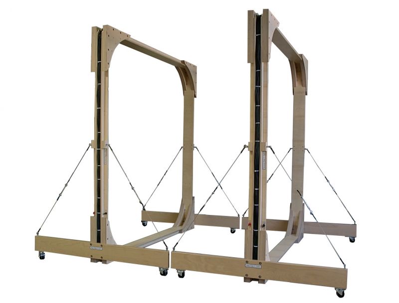
The Helmholtz-Coils are especially designed to generate precisely defined magnetic fields from DC to ca. 5 kHz, e.g. according to SAE J551-17. The generated fields are in a strongly linear relation to the coil current. The field strength can be calculated exactly by analytical (or numerical) methods, based on the coils' geometry, the number of turns and the coil current. Therefore, the HHS 5230-100 is ideally suited for immunity testing against magnetic fields in the automotive sector. Due to the generously dimensioned winding packets, it is possible to generate magnetic fields up to approx. 800 A/m for short times. Typical applications are magnetic immunity testing to whole vehicles according to SAEJ551-17 (Vehicle Electromagnetic Immunity – Power Line Magnetic Fields). When generating magnetic fields with Helmholtz coils, the coil current is directly proportional to the magnetic fieldstrength.
The calibration of the magnetic field is finally traceable to a current measurement (or to a voltage drop across a known resistor). The Helmholtz Coil itself does not require a calibration. Alternatively, a small loop sensor can be used to determine the actual field strength.
Installation:
The setup of the coils is described in the following part of the manual: “Assembly Instructions for Helmholtz Coil Pair HHS 5230”
The Helmholtz-Coils should be installed on the floor in a sufficiently large seperation from sources of unintentional magnetic fields, e.g. transformers in power supplies, conductors carrying high currents, computer monitors, loudspeakers, cathode ray tubes (CRT) and more All kind of magnetic material (e.g. steel, Nickel, Cobalt) should be removed from the near surrounding of the coil. The wires which are used to connect the current source with the Helmholtz-Coil should be twisted to avoid an unwanted injection of magnetic flux.
The coil terminals are assigned with the characters A, B, C and D.
During operation of the coils the terminals must show in one direction. Otherwise, there will be a deletion of the magnetic field in the middle between the coils.
- –£–∑–Ω–∞–π—Ç–µ –ø–æ —Ç–µ–ª.: +7 (495) 105 96 88
- –ù–∞–ø–∏—à–∏—Ç–µ –Ω–∞–º –ø–∏—Å—å–º–æ: info@micro-electronics.ru
- –£–∑–Ω–∞–π—Ç–µ –ø–æ —Ç–µ–ª.: +7 (495) 105 96 88
- –ù–∞–ø–∏—à–∏—Ç–µ –Ω–∞–º –ø–∏—Å—å–º–æ: info@micro-electronics.ru
| HHS 5230-100 - Helmholtz Coils | |
| Number of turns: | 100 |
| Maximum Coil Current: | 16 A (5 min.) |
| Nominal Coil Current: | 8 A continuous |
| Max. Magn. Field Strength: | 650 A/m @ coil Dist. =1.8 m |
| Nominal Magn. Field Strength: | 325 A/m @ coil Dist. = 1.8 m |
| Magn. Field Strength, 1 A Coil Current: | 50.8 A/m (coil Dist. 1.13 m) |
| Maximum Coil Separation: | >1.13 m |
| Coil Separation for best uniformity: | 1.8 m |
| Mechanical Dimensions: | W:2.0 m x H:3.10 m x B:3.18 m |
| Ground Clearence: | 0.12 m |
| Usable Frequency Range: | DC - 5 kHz |
| Resonance Frequency (per Coil): | >10 kHz, typ. 13 kHz |
| Weight (per Coil): | 190 kg |
| Recommended Accessories: | NFCN 9731-100 |
–¢–æ–≤–∞—Ä |
|
|
|
–ú–æ–¥–µ–ª–∏ –∏ –û–ø—Ü–∏–∏ |
–û–ø–∏—Å–∞–Ω–∏–µ |
–¶–µ–Ω–∞ | –ó–∞–∫–∞–∑–∞—Ç—å |
0
| –ú–æ–¥–µ–ª–∏ |
|
HHS 5230-100
|
–ö–∞—Ç—É—à–∫–∞ –ì–µ–ª—å–º–≥–æ–ª—å—Ü–∞ HHS 5230-100
|
–ü–æ –∑–∞–ø—Ä–æ—Å—É |
1
| –Ý–µ–∫–æ–º–µ–Ω–¥—É–µ–º—ã–µ –∞–∫—Å–µ—Å—Å—É–∞—Ä—ã |
|
NFCN 9731-100
|
–°—Ö–µ–º–∞ –∫–æ–º–ø–µ–Ω—Å–∞—Ü–∏–∏ NFCN 9731-100 –¥–ª—è HHS 5230-100
|
–ü–æ –∑–∞–ø—Ä–æ—Å—É |


