


–ù–∞–ª–∏—á–∏–µ: –ü–æ –∑–∞–ø—Ä–æ—Å—É–ü–æ –∑–∞–ø—Ä–æ—Å—É –ü–æ –∑–∞–ø—Ä–æ—Å—É –ü–æ –∑–∞–ø—Ä–æ—Å—É

–ê–º–µ—Ä–∏–∫–∞–Ω—Å–∫–∞—è –∫–æ–º–ø–∞–Ω–∏—è Keysight Technologies –Ω–∞—á–∞–ª–∞ —Å–≤–æ—é –∏—Å—Ç–æ—Ä–∏—é –≤ 1930-—Ö –≥–æ–¥–∞—Ö –ø—Ä–æ—à–ª–æ–≥–æ –≤–µ–∫–∞. –°–µ–≥–æ–¥–Ω—è ‚Äì —ç—Ç–æ –ª–∏–¥–µ—Ä –≤ –ø—Ä–æ–∏–∑–≤–æ–¥—Å—Ç–≤–µ –∏–∑–º–µ—Ä–∏—Ç–µ–ª—å–Ω–æ–≥–æ –æ–±–æ—Ä—É–¥–æ–≤–∞–Ω–∏—è –∏ –°–ê–ü–Ý (—Å–∏—Å—Ç–µ–º –∞–≤—Ç–æ–º–∞—Ç–∏–∑–∏—Ä–æ–≤–∞–Ω–Ω–æ–≥–æ –ø—Ä–æ–µ–∫—Ç–∏—Ä–æ–≤–∞–Ω–∏—è). Keysight Technologies –ø—Ä–µ–¥–ª–∞–≥–∞–µ—Ç –∏–Ω—Ç–µ–≥—Ä–∏—Ä–æ–≤–∞–Ω–Ω—ã–µ —Ä–µ—à–µ–Ω–∏—è, –æ–±—ä–µ–¥–∏–Ω—è—é—â–∏–µ –∏–∑–º–µ—Ä–µ–Ω–∏—è, —ç–∫—Å—Ç—Ä–∞–∫—Ü–∏—é –ø–∞—Ä–∞–º–µ—Ç—Ä–æ–≤ –∏ –≤–µ—Ä–∏—Ñ–∏–∫–∞—Ü–∏—é —Ä–∞–∑—Ä–∞–±–æ—Ç–æ–∫.
Компания Keysight Technologies производит осциллографы, анализаторы, измерители, генераторы, источники питания, а также… подробнее
–§—É–Ω–∫—Ü–∏–æ–Ω–∞–ª—å–Ω—ã–µ –≤–æ–∑–º–æ–∂–Ω–æ—Å—Ç–∏
- –ß–∞—Å—Ç–æ—Ç–∞ –¥–∏—Å–∫—Ä–µ—Ç–∏–∑–∞—Ü–∏–∏: –¥–æ 65 –ì–≤—ã–±./—Å
- –í—ã—Å–æ–∫–∞—è –ø–ª–æ—Ç–Ω–æ—Å—Ç—å –∫–∞–Ω–∞–ª–æ–≤: 1, 2 –∏–ª–∏ 4 –∫–∞–Ω–∞–ª–∞ –Ω–∞ –º–æ–¥—É–ª—å
- –í—Å—Ç—Ä–æ–µ–Ω–Ω–∞—è —Ñ—É–Ω–∫—Ü–∏—è –∫–∞–ª–∏–±—Ä–æ–≤–∫–∏ —á–∞—Å—Ç–æ—Ç–Ω–æ–π –∏ —Ñ–∞–∑–æ–≤–æ–π —Ö–∞—Ä–∞–∫—Ç–µ—Ä–∏—Å—Ç–∏–∫–∏
- –í—Å—Ç—Ä–æ–µ–Ω–Ω—ã–µ —Ñ—É–Ω–∫—Ü–∏–∏ —Ü–∏—Ñ—Ä–æ–≤–æ–π –æ–±—Ä–∞–±–æ—Ç–∫–∏ —Å–∏–≥–Ω–∞–ª–æ–≤ –æ–±–µ—Å–ø–µ—á–∏–≤–∞—é—Ç —Ñ–æ—Ä–º–∏—Ä–æ–≤–∞–Ω–∏–µ —Å–∏–≥–Ω–∞–ª–æ–≤ –∏ –∏—Å–∫–∞–∂–µ–Ω–∏–π –≤ —Ä–µ–∂–∏–º–µ —Ä–µ–∞–ª—å–Ω–æ–≥–æ –≤—Ä–µ–º–µ–Ω–∏
–û—Å–Ω–æ–≤–Ω—ã–µ —Ö–∞—Ä–∞–∫—Ç–µ—Ä–∏—Å—Ç–∏–∫–∏
- –ê–Ω–∞–ª–æ–≥–æ–≤–∞—è –ø–æ–ª–æ—Å–∞ —á–∞—Å—Ç–æ—Ç: –¥–æ 20 –ì–ì—Ü
- –í—ã—Ö–æ–¥–Ω–æ–µ –Ω–∞–ø—Ä—è–∂–µ–Ω–∏–µ: –¥–æ 1 –í (—Ä–∞–∑–º–∞—Ö) –¥–ª—è –Ω–µ—Å–∏–º–º–µ—Ç—Ä–∏—á–Ω—ã—Ö —Å–∏–≥–Ω–∞–ª–æ–≤ –∏ –¥–æ 2 –í (—Ä–∞–∑–º–∞—Ö) –¥–ª—è –¥–∏—Ñ—Ñ–µ—Ä–µ–Ω—Ü–∏–∞–ª—å–Ω—ã—Ö —Å–∏–≥–Ω–∞–ª–æ–≤
- –§–æ—Ä–º–∏—Ä–æ–≤–∞–Ω–∏–µ —Å–∏–≥–Ω–∞–ª–æ–≤ —Å–æ —Å–∫–æ—Ä–æ—Å—Ç—å—é –¥–æ 32 –ì–±–æ–¥ –∏ –≤—ã—à–µ
–°–∏—Å—Ç–µ–º–∞ —Å –≥–æ—Ç–æ–≤–æ–π –∫–æ–Ω—Ñ–∏–≥—É—Ä–∞—Ü–∏–µ–π M8195S, –≤–∫–ª—é—á–∞—é—â–∞—è:
- –ì–µ–Ω–µ—Ä–∞—Ç–æ—Ä —Å–∏–≥–Ω–∞–ª–æ–≤ –ø—Ä–æ–∏–∑–≤–æ–ª—å–Ω–æ–π —Ñ–æ—Ä–º—ã M8195A
- –®–∞—Å—Å–∏ –≤ —Ñ–æ—Ä–º–∞—Ç–µ AXIe
- –í—Å—Ç—Ä–æ–µ–Ω–Ω—ã–π –∫–æ–Ω—Ç—Ä–æ–ª–ª–µ—Ä –∏–ª–∏ —Å—Ä–µ–¥—Å—Ç–≤–∞ –ø–æ–¥–∫–ª—é—á–µ–Ω–∏—è –∫ –≤–Ω–µ—à–Ω–µ–º—É –∫–æ–º–ø—å—é—Ç–µ—Ä—É
–û—Å–Ω–æ–≤–Ω—ã–µ –æ–±–ª–∞—Å—Ç–∏ –ø—Ä–∏–º–µ–Ω–µ–Ω–∏—è
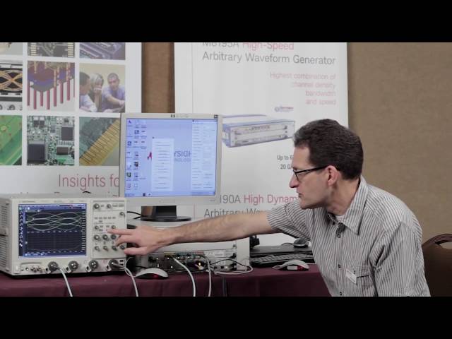
–ü–æ –º–µ—Ä–µ —Ç–æ–≥–æ, –∫–∞–∫ —É—Å—Ç—Ä–æ–π—Å—Ç–≤–∞ –∏ –∏–Ω—Ç–µ—Ä—Ñ–µ–π—Å—ã —Å—Ç–∞–Ω–æ–≤—è—Ç—Å—è –≤—Å–µ –±–æ–ª–µ–µ —Å–ª–æ–∂–Ω—ã–º–∏ –∏ –±—ã—Å—Ç—Ä–æ–¥–µ–π—Å—Ç–≤—É—é—â–∏–º–∏, –≥–µ–Ω–µ—Ä–∞—Ç–æ—Ä —Å–∏–≥–Ω–∞–ª–æ–≤ –ø—Ä–æ–∏–∑–≤–æ–ª—å–Ω–æ–π —Ñ–æ—Ä–º—ã M8195A –æ–±–µ—Å–ø–µ—á–∏–≤–∞–µ—Ç –≥–∏–±–∫–∏–µ –≤–æ–∑–º–æ–∂–Ω–æ—Å—Ç–∏ –ø–æ —Å–æ–∑–¥–∞–Ω–∏—é —Å–∏–≥–Ω–∞–ª–æ–≤ –≤ –æ–±–ª–∞—Å—Ç–∏ –ø–µ—Ä—Å–ø–µ–∫—Ç–∏–≤–Ω—ã—Ö –∏—Å—Å–ª–µ–¥–æ–≤–∞–Ω–∏–π, –¥–ª—è —Ü–∏—Ñ—Ä–æ–≤—ã—Ö –ø—Ä–∏–ª–æ–∂–µ–Ω–∏–π, –æ–ø—Ç–∏—á–µ—Å–∫–∏—Ö –∏ —ç–ª–µ–∫—Ç—Ä–∏—á–µ—Å–∫–∏—Ö —Å–∏—Å—Ç–µ–º —Å–≤—è–∑–∏, —à–∏—Ä–æ–∫–æ–ø–æ–ª–æ—Å–Ω—ã—Ö —Ä–∞–¥–∏–æ–ª–æ–∫–∞—Ü–∏–æ–Ω–Ω—ã—Ö —Å–∏—Å—Ç–µ–º –∏ —Å—Ä–µ–¥—Å—Ç–≤ —Å–ø—É—Ç–Ω–∏–∫–æ–≤–æ–π —Å–≤—è–∑–∏.
- Когерентные оптические системы — один модуль M8195A позволяет формировать две пары сигналов с I/Q модуляцией (двойная поляризация = четыре канала) со скоростью 32 Гбод и выше
- Цифровые многоуровневые и многоканальные сигналы — формирование сигналов NRZ, PAM4, PAM8, DMT и других видов сигналов со скоростью до 32 Гбод; возможность внесения джиттера, межсимвольных помех, шума и других искажений
- Исследования в области физики, химии, электроники — формирование любых сигналов произвольной формы, задаваемых математическими формулами, сверхкоротких прецизионных импульсов и сверхширокополосных импульсов с линейной частотной модуляцией
- Широкополосные ВЧ и СВЧ системы — формирование сверхширокополосных ВЧ сигналов с мгновенной полосой от 0 до 20 ГГц для приложений в аэрокосмической, оборонной и телекоммуникационной отраслях
–û–ø–∏—Å–∞–Ω–∏–µ
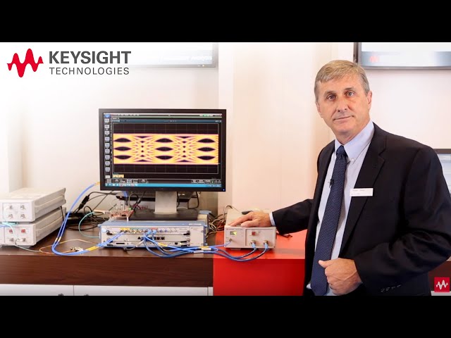
–ë—ã—Å—Ç—Ä–æ–¥–µ–π—Å—Ç–≤—É—é—â–∏–π –≥–µ–Ω–µ—Ä–∞—Ç–æ—Ä —Å–∏–≥–Ω–∞–ª–æ–≤ –ø—Ä–æ–∏–∑–≤–æ–ª—å–Ω–æ–π —Ñ–æ—Ä–º—ã Keysight M8195A –∏–º–µ–µ—Ç –∞–Ω–∞–ª–æ–≥–æ–≤—É—é –ø–æ–ª–æ—Å—É —á–∞—Å—Ç–æ—Ç –¥–æ 20 –ì–ì—Ü, —á–∞—Å—Ç–æ—Ç—É –¥–∏—Å–∫—Ä–µ—Ç–∏–∑–∞—Ü–∏–∏ –¥–æ 65 –ì–≤—ã–±./—Å –∏ –¥–æ 4 –∫–∞–Ω–∞–ª–æ–≤ –≤ –∫–∞–∂–¥–æ–º 1-—Å–ª–æ—Ç–æ–≤–æ–º –º–æ–¥—É–ª–µ –≤ —Ñ–æ—Ä–º–∞—Ç–µ AXIe. –ü–æ –º–µ—Ä–µ —Ç–æ–≥–æ, –∫–∞–∫ —É—Å—Ç—Ä–æ–π—Å—Ç–≤–∞ –∏ –∏–Ω—Ç–µ—Ä—Ñ–µ–π—Å—ã —Å—Ç–∞–Ω–æ–≤—è—Ç—Å—è –≤—Å–µ –±–æ–ª–µ–µ –±—ã—Å—Ç—Ä–æ–¥–µ–π—Å—Ç–≤—É—é—â–∏–º–∏ –∏ –±–æ–ª–µ–µ —Å–ª–æ–∂–Ω—ã–º–∏, –≥–µ–Ω–µ—Ä–∞—Ç–æ—Ä Keysight M8195A –æ–±–µ—Å–ø–µ—á–∏–≤–∞–µ—Ç –≥–∏–±–∫–∏–µ –≤–æ–∑–º–æ–∂–Ω–æ—Å—Ç–∏ –ø–æ —Ñ–æ—Ä–º–∏—Ä–æ–≤–∞–Ω–∏—é —Å–∏–≥–Ω–∞–ª–æ–≤, –∏—Å–ø–æ–ª—å–∑—É–µ–º—ã—Ö –≤ –æ–±–ª–∞—Å—Ç–∏ —Ä–∞–∑—Ä–∞–±–æ—Ç–∫–∏ —Ü–∏—Ñ—Ä–æ–≤—ã—Ö –ø—Ä–∏–ª–æ–∂–µ–Ω–∏–π, –≤ —Ö–æ–¥–µ –ø–µ—Ä—Å–ø–µ–∫—Ç–∏–≤–Ω—ã—Ö –∏—Å—Å–ª–µ–¥–æ–≤–∞–Ω–∏–π, –¥–ª—è —Ç–µ—Å—Ç–∏—Ä–æ–≤–∞–Ω–∏—è —à–∏—Ä–æ–∫–æ–ø–æ–ª–æ—Å–Ω—ã—Ö —Ä–∞–¥–∞—Ä–æ–≤, —Å—Ä–µ–¥—Å—Ç–≤ —Å–ø—É—Ç–Ω–∏–∫–æ–≤–æ–π —Å–≤—è–∑–∏ –∏ –æ–ø—Ç–∏—á–µ—Å–∫–∏—Ö —Å–∏—Å—Ç–µ–º –ø–µ—Ä–µ–¥–∞—á–∏ –¥–∞–Ω–Ω—ã—Ö.
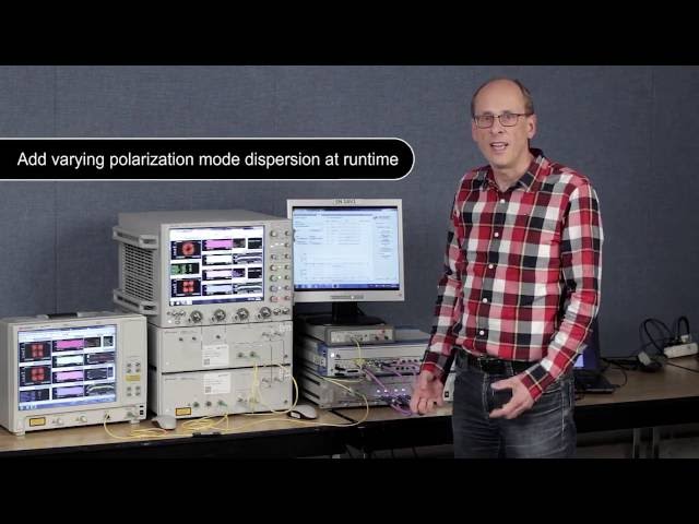
–£–Ω–∏–∫–∞–ª—å–Ω—ã–π —Ä–µ–∂–∏–º —Ä–µ–∞–ª—å–Ω–æ–≥–æ –≤—Ä–µ–º–µ–Ω–∏ –ø–æ–∑–≤–æ–ª—è–µ—Ç —Å–æ–∫—Ä–∞—Ç–∏—Ç—å –≤—Ä–µ–º—è —Ç–µ—Å—Ç–∏—Ä–æ–≤–∞–Ω–∏—è –≤ —Å–æ—Ç–Ω–∏ —Ä–∞–∑. –§–∏–ª—å—Ç—Ä—ã —Å –∫–æ–Ω–µ—á–Ω–æ–π –∏–º–ø—É–ª—å—Å–Ω–æ–π —Ö–∞—Ä–∞–∫—Ç–µ—Ä–∏—Å—Ç–∏–∫–æ–π –∏ –¥—Ä—É–≥–∏–µ —Ñ—É–Ω–∫—Ü–∏–∏ —Ü–∏—Ñ—Ä–æ–≤–æ–π –æ–±—Ä–∞–±–æ—Ç–∫–∏ —Å–∏–≥–Ω–∞–ª–æ–≤ –∏—Å–ø–æ–ª—å–∑—É—é—Ç—Å—è –¥–ª—è —Ñ–æ—Ä–º–∏—Ä–æ–≤–∞–Ω–∏—è –∏–º–ø—É–ª—å—Å–æ–≤ –∏ –∏–∑–º–µ–Ω–µ–Ω–∏—è —ç–∫—Å—Ç—Ä–µ–º–∞–ª—å–Ω—ã—Ö —É—Å–ª–æ–≤–∏–π —Ç–µ—Å—Ç–∏—Ä–æ–≤–∞–Ω–∏—è –æ–ø—Ç–∏—á–µ—Å–∫–∏—Ö —Å–∏—Å—Ç–µ–º, –Ω–∞–ø—Ä–∏–º–µ—Ä, –ø–æ–ª—è—Ä–∏–∑–∞—Ü–∏–æ–Ω–Ω–æ–π –º–æ–¥–æ–≤–æ–π –¥–∏—Å–ø–µ—Ä—Å–∏–∏ (PMD) –∏–ª–∏ –≤–µ–ª–∏—á–∏–Ω—ã —Ñ–∞–∑–æ–≤–æ–≥–æ —à—É–º–∞.
Генератор сигналов произвольной формы Keysight M8195A — это повышение эффективности тестирования многоканальных высокоскоростных устройств благодаря возможности использования режима реального времени, функции создания последовательностей и глубокой памяти.
–î–æ–ø–æ–ª–Ω–∏—Ç–µ–ª—å–Ω–∞—è –∏–Ω—Ñ–æ—Ä–º–∞—Ü–∏—è
–ì–µ–Ω–µ—Ä–∞—Ç–æ—Ä —Å–∏–≥–Ω–∞–ª–æ–≤ M8195A –º–æ–∂–µ—Ç –ø–æ—Å—Ç–∞–≤–ª—è—Ç—å—Å—è –≤ —Å–æ—Å—Ç–∞–≤–µ —Å–∏—Å—Ç–µ–º–Ω–æ–≥–æ –∫–æ–º–ø–ª–µ–∫—Ç–∞ M8195S, –∫–æ—Ç–æ—Ä—ã–π –æ–±–µ—Å–ø–µ—á–∏–≤–∞–µ—Ç –≥–∏–±–∫—É—é –∫–æ–Ω—Ñ–∏–≥—É—Ä–∞—Ü–∏—é –≤ –∑–∞–≤–∏—Å–∏–º–æ—Å—Ç–∏ –æ—Ç –Ω–µ–æ–±—Ö–æ–¥–∏–º–æ–≥–æ –∫–æ–ª–∏—á–µ—Å—Ç–≤–∞ –∫–∞–Ω–∞–ª–æ–≤.
–ü–æ–º–∏–º–æ —Å–∞–º–æ–≥–æ –º–æ–¥—É–ª—è –≥–µ–Ω–µ—Ä–∞—Ç–æ—Ä–∞ –∫–æ–Ω—Ñ–∏–≥—É—Ä–∞—Ü–∏—è —Å–∏—Å—Ç–µ–º—ã –≤–∫–ª—é—á–∞–µ—Ç —à–∞—Å—Å–∏ –≤ —Ñ–æ—Ä–º–∞—Ç–µ AXIe, –≤—Å—Ç—Ä–æ–µ–Ω–Ω—ã–π –∫–æ–Ω—Ç—Ä–æ–ª–ª–µ—Ä –∏–ª–∏ —Å—Ä–µ–¥—Å—Ç–≤–∞ –ø–æ–¥–∫–ª—é—á–µ–Ω–∏—è –∫ –≤–Ω–µ—à–Ω–µ–º—É –∫–æ–º–ø—å—é—Ç–µ—Ä—É.
–§—É–Ω–∫—Ü–∏–æ–Ω–∞–ª—å–Ω—ã–µ –≤–æ–∑–º–æ–∂–Ω–æ—Å—Ç–∏
- –ß–∞—Å—Ç–æ—Ç–∞ –¥–∏—Å–∫—Ä–µ—Ç–∏–∑–∞—Ü–∏–∏: –¥–æ 65 –ì–≤—ã–±./—Å
- –í—ã—Å–æ–∫–∞—è –ø–ª–æ—Ç–Ω–æ—Å—Ç—å –∫–∞–Ω–∞–ª–æ–≤: 1, 2 –∏–ª–∏ 4 –∫–∞–Ω–∞–ª–∞ –Ω–∞ –º–æ–¥—É–ª—å
- –í—Å—Ç—Ä–æ–µ–Ω–Ω–∞—è —Ñ—É–Ω–∫—Ü–∏—è –∫–∞–ª–∏–±—Ä–æ–≤–∫–∏ —á–∞—Å—Ç–æ—Ç–Ω–æ–π –∏ —Ñ–∞–∑–æ–≤–æ–π —Ö–∞—Ä–∞–∫—Ç–µ—Ä–∏—Å—Ç–∏–∫–∏
- –í—Å—Ç—Ä–æ–µ–Ω–Ω—ã–µ —Ñ—É–Ω–∫—Ü–∏–∏ —Ü–∏—Ñ—Ä–æ–≤–æ–π –æ–±—Ä–∞–±–æ—Ç–∫–∏ —Å–∏–≥–Ω–∞–ª–æ–≤ –æ–±–µ—Å–ø–µ—á–∏–≤–∞—é—Ç —Ñ–æ—Ä–º–∏—Ä–æ–≤–∞–Ω–∏–µ —Å–∏–≥–Ω–∞–ª–æ–≤ –∏ –∏—Å–∫–∞–∂–µ–Ω–∏–π –≤ —Ä–µ–∂–∏–º–µ —Ä–µ–∞–ª—å–Ω–æ–≥–æ –≤—Ä–µ–º–µ–Ω–∏
–û—Å–Ω–æ–≤–Ω—ã–µ —Ö–∞—Ä–∞–∫—Ç–µ—Ä–∏—Å—Ç–∏–∫–∏
- –ê–Ω–∞–ª–æ–≥–æ–≤–∞—è –ø–æ–ª–æ—Å–∞ —á–∞—Å—Ç–æ—Ç: –¥–æ 20 –ì–ì—Ü
- –í—ã—Ö–æ–¥–Ω–æ–µ –Ω–∞–ø—Ä—è–∂–µ–Ω–∏–µ: –¥–æ 1 –í (—Ä–∞–∑–º–∞—Ö) –¥–ª—è –Ω–µ—Å–∏–º–º–µ—Ç—Ä–∏—á–Ω—ã—Ö —Å–∏–≥–Ω–∞–ª–æ–≤ –∏ –¥–æ 2 –í (—Ä–∞–∑–º–∞—Ö) –¥–ª—è –¥–∏—Ñ—Ñ–µ—Ä–µ–Ω—Ü–∏–∞–ª—å–Ω—ã—Ö —Å–∏–≥–Ω–∞–ª–æ–≤
- –§–æ—Ä–º–∏—Ä–æ–≤–∞–Ω–∏–µ —Å–∏–≥–Ω–∞–ª–æ–≤ —Å–æ —Å–∫–æ—Ä–æ—Å—Ç—å—é –¥–æ 32 –ì–±–æ–¥ –∏ –≤—ã—à–µ
–°–∏—Å—Ç–µ–º–∞ —Å –≥–æ—Ç–æ–≤–æ–π –∫–æ–Ω—Ñ–∏–≥—É—Ä–∞—Ü–∏–µ–π M8195S, –≤–∫–ª—é—á–∞—é—â–∞—è:
- –ì–µ–Ω–µ—Ä–∞—Ç–æ—Ä —Å–∏–≥–Ω–∞–ª–æ–≤ –ø—Ä–æ–∏–∑–≤–æ–ª—å–Ω–æ–π —Ñ–æ—Ä–º—ã M8195A
- –®–∞—Å—Å–∏ –≤ —Ñ–æ—Ä–º–∞—Ç–µ AXIe
- –í—Å—Ç—Ä–æ–µ–Ω–Ω—ã–π –∫–æ–Ω—Ç—Ä–æ–ª–ª–µ—Ä –∏–ª–∏ —Å—Ä–µ–¥—Å—Ç–≤–∞ –ø–æ–¥–∫–ª—é—á–µ–Ω–∏—è –∫ –≤–Ω–µ—à–Ω–µ–º—É –∫–æ–º–ø—å—é—Ç–µ—Ä—É
–û—Å–Ω–æ–≤–Ω—ã–µ –æ–±–ª–∞—Å—Ç–∏ –ø—Ä–∏–º–µ–Ω–µ–Ω–∏—è
–ü–æ –º–µ—Ä–µ —Ç–æ–≥–æ, –∫–∞–∫ —É—Å—Ç—Ä–æ–π—Å—Ç–≤–∞ –∏ –∏–Ω—Ç–µ—Ä—Ñ–µ–π—Å—ã —Å—Ç–∞–Ω–æ–≤—è—Ç—Å—è –≤—Å–µ –±–æ–ª–µ–µ —Å–ª–æ–∂–Ω—ã–º–∏ –∏ –±—ã—Å—Ç—Ä–æ–¥–µ–π—Å—Ç–≤—É—é—â–∏–º–∏, –≥–µ–Ω–µ—Ä–∞—Ç–æ—Ä —Å–∏–≥–Ω–∞–ª–æ–≤ –ø—Ä–æ–∏–∑–≤–æ–ª—å–Ω–æ–π —Ñ–æ—Ä–º—ã M8195A –æ–±–µ—Å–ø–µ—á–∏–≤–∞–µ—Ç –≥–∏–±–∫–∏–µ –≤–æ–∑–º–æ–∂–Ω–æ—Å—Ç–∏ –ø–æ —Å–æ–∑–¥–∞–Ω–∏—é —Å–∏–≥–Ω–∞–ª–æ–≤ –≤ –æ–±–ª–∞—Å—Ç–∏ –ø–µ—Ä—Å–ø–µ–∫—Ç–∏–≤–Ω—ã—Ö –∏—Å—Å–ª–µ–¥–æ–≤–∞–Ω–∏–π, –¥–ª—è —Ü–∏—Ñ—Ä–æ–≤—ã—Ö –ø—Ä–∏–ª–æ–∂–µ–Ω–∏–π, –æ–ø—Ç–∏—á–µ—Å–∫–∏—Ö –∏ —ç–ª–µ–∫—Ç—Ä–∏—á–µ—Å–∫–∏—Ö —Å–∏—Å—Ç–µ–º —Å–≤—è–∑–∏, —à–∏—Ä–æ–∫–æ–ø–æ–ª–æ—Å–Ω—ã—Ö —Ä–∞–¥–∏–æ–ª–æ–∫–∞—Ü–∏–æ–Ω–Ω—ã—Ö —Å–∏—Å—Ç–µ–º –∏ —Å—Ä–µ–¥—Å—Ç–≤ —Å–ø—É—Ç–Ω–∏–∫–æ–≤–æ–π —Å–≤—è–∑–∏.
- Когерентные оптические системы — один модуль M8195A позволяет формировать две пары сигналов с I/Q модуляцией (двойная поляризация = четыре канала) со скоростью 32 Гбод и выше
- Цифровые многоуровневые и многоканальные сигналы — формирование сигналов NRZ, PAM4, PAM8, DMT и других видов сигналов со скоростью до 32 Гбод; возможность внесения джиттера, межсимвольных помех, шума и других искажений
- Исследования в области физики, химии, электроники — формирование любых сигналов произвольной формы, задаваемых математическими формулами, сверхкоротких прецизионных импульсов и сверхширокополосных импульсов с линейной частотной модуляцией
- Широкополосные ВЧ и СВЧ системы — формирование сверхширокополосных ВЧ сигналов с мгновенной полосой от 0 до 20 ГГц для приложений в аэрокосмической, оборонной и телекоммуникационной отраслях
–û–ø–∏—Å–∞–Ω–∏–µ
–ë—ã—Å—Ç—Ä–æ–¥–µ–π—Å—Ç–≤—É—é—â–∏–π –≥–µ–Ω–µ—Ä–∞—Ç–æ—Ä —Å–∏–≥–Ω–∞–ª–æ–≤ –ø—Ä–æ–∏–∑–≤–æ–ª—å–Ω–æ–π —Ñ–æ—Ä–º—ã Keysight M8195A –∏–º–µ–µ—Ç –∞–Ω–∞–ª–æ–≥–æ–≤—É—é –ø–æ–ª–æ—Å—É —á–∞—Å—Ç–æ—Ç –¥–æ 20 –ì–ì—Ü, —á–∞—Å—Ç–æ—Ç—É –¥–∏—Å–∫—Ä–µ—Ç–∏–∑–∞—Ü–∏–∏ –¥–æ 65 –ì–≤—ã–±./—Å –∏ –¥–æ 4 –∫–∞–Ω–∞–ª–æ–≤ –≤ –∫–∞–∂–¥–æ–º 1-—Å–ª–æ—Ç–æ–≤–æ–º –º–æ–¥—É–ª–µ –≤ —Ñ–æ—Ä–º–∞—Ç–µ AXIe. –ü–æ –º–µ—Ä–µ —Ç–æ–≥–æ, –∫–∞–∫ —É—Å—Ç—Ä–æ–π—Å—Ç–≤–∞ –∏ –∏–Ω—Ç–µ—Ä—Ñ–µ–π—Å—ã —Å—Ç–∞–Ω–æ–≤—è—Ç—Å—è –≤—Å–µ –±–æ–ª–µ–µ –±—ã—Å—Ç—Ä–æ–¥–µ–π—Å—Ç–≤—É—é—â–∏–º–∏ –∏ –±–æ–ª–µ–µ —Å–ª–æ–∂–Ω—ã–º–∏, –≥–µ–Ω–µ—Ä–∞—Ç–æ—Ä Keysight M8195A –æ–±–µ—Å–ø–µ—á–∏–≤–∞–µ—Ç –≥–∏–±–∫–∏–µ –≤–æ–∑–º–æ–∂–Ω–æ—Å—Ç–∏ –ø–æ —Ñ–æ—Ä–º–∏—Ä–æ–≤–∞–Ω–∏—é —Å–∏–≥–Ω–∞–ª–æ–≤, –∏—Å–ø–æ–ª—å–∑—É–µ–º—ã—Ö –≤ –æ–±–ª–∞—Å—Ç–∏ —Ä–∞–∑—Ä–∞–±–æ—Ç–∫–∏ —Ü–∏—Ñ—Ä–æ–≤—ã—Ö –ø—Ä–∏–ª–æ–∂–µ–Ω–∏–π, –≤ —Ö–æ–¥–µ –ø–µ—Ä—Å–ø–µ–∫—Ç–∏–≤–Ω—ã—Ö –∏—Å—Å–ª–µ–¥–æ–≤–∞–Ω–∏–π, –¥–ª—è —Ç–µ—Å—Ç–∏—Ä–æ–≤–∞–Ω–∏—è —à–∏—Ä–æ–∫–æ–ø–æ–ª–æ—Å–Ω—ã—Ö —Ä–∞–¥–∞—Ä–æ–≤, —Å—Ä–µ–¥—Å—Ç–≤ —Å–ø—É—Ç–Ω–∏–∫–æ–≤–æ–π —Å–≤—è–∑–∏ –∏ –æ–ø—Ç–∏—á–µ—Å–∫–∏—Ö —Å–∏—Å—Ç–µ–º –ø–µ—Ä–µ–¥–∞—á–∏ –¥–∞–Ω–Ω—ã—Ö.
–£–Ω–∏–∫–∞–ª—å–Ω—ã–π —Ä–µ–∂–∏–º —Ä–µ–∞–ª—å–Ω–æ–≥–æ –≤—Ä–µ–º–µ–Ω–∏ –ø–æ–∑–≤–æ–ª—è–µ—Ç —Å–æ–∫—Ä–∞—Ç–∏—Ç—å –≤—Ä–µ–º—è —Ç–µ—Å—Ç–∏—Ä–æ–≤–∞–Ω–∏—è –≤ —Å–æ—Ç–Ω–∏ —Ä–∞–∑. –§–∏–ª—å—Ç—Ä—ã —Å –∫–æ–Ω–µ—á–Ω–æ–π –∏–º–ø—É–ª—å—Å–Ω–æ–π —Ö–∞—Ä–∞–∫—Ç–µ—Ä–∏—Å—Ç–∏–∫–æ–π –∏ –¥—Ä—É–≥–∏–µ —Ñ—É–Ω–∫—Ü–∏–∏ —Ü–∏—Ñ—Ä–æ–≤–æ–π –æ–±—Ä–∞–±–æ—Ç–∫–∏ —Å–∏–≥–Ω–∞–ª–æ–≤ –∏—Å–ø–æ–ª—å–∑—É—é—Ç—Å—è –¥–ª—è —Ñ–æ—Ä–º–∏—Ä–æ–≤–∞–Ω–∏—è –∏–º–ø—É–ª—å—Å–æ–≤ –∏ –∏–∑–º–µ–Ω–µ–Ω–∏—è —ç–∫—Å—Ç—Ä–µ–º–∞–ª—å–Ω—ã—Ö —É—Å–ª–æ–≤–∏–π —Ç–µ—Å—Ç–∏—Ä–æ–≤–∞–Ω–∏—è –æ–ø—Ç–∏—á–µ—Å–∫–∏—Ö —Å–∏—Å—Ç–µ–º, –Ω–∞–ø—Ä–∏–º–µ—Ä, –ø–æ–ª—è—Ä–∏–∑–∞—Ü–∏–æ–Ω–Ω–æ–π –º–æ–¥–æ–≤–æ–π –¥–∏—Å–ø–µ—Ä—Å–∏–∏ (PMD) –∏–ª–∏ –≤–µ–ª–∏—á–∏–Ω—ã —Ñ–∞–∑–æ–≤–æ–≥–æ —à—É–º–∞.
Генератор сигналов произвольной формы Keysight M8195A — это повышение эффективности тестирования многоканальных высокоскоростных устройств благодаря возможности использования режима реального времени, функции создания последовательностей и глубокой памяти.
–î–æ–ø–æ–ª–Ω–∏—Ç–µ–ª—å–Ω–∞—è –∏–Ω—Ñ–æ—Ä–º–∞—Ü–∏—è
–ì–µ–Ω–µ—Ä–∞—Ç–æ—Ä —Å–∏–≥–Ω–∞–ª–æ–≤ M8195A –º–æ–∂–µ—Ç –ø–æ—Å—Ç–∞–≤–ª—è—Ç—å—Å—è –≤ —Å–æ—Å—Ç–∞–≤–µ —Å–∏—Å—Ç–µ–º–Ω–æ–≥–æ –∫–æ–º–ø–ª–µ–∫—Ç–∞ M8195S, –∫–æ—Ç–æ—Ä—ã–π –æ–±–µ—Å–ø–µ—á–∏–≤–∞–µ—Ç –≥–∏–±–∫—É—é –∫–æ–Ω—Ñ–∏–≥—É—Ä–∞—Ü–∏—é –≤ –∑–∞–≤–∏—Å–∏–º–æ—Å—Ç–∏ –æ—Ç –Ω–µ–æ–±—Ö–æ–¥–∏–º–æ–≥–æ –∫–æ–ª–∏—á–µ—Å—Ç–≤–∞ –∫–∞–Ω–∞–ª–æ–≤.
–ü–æ–º–∏–º–æ —Å–∞–º–æ–≥–æ –º–æ–¥—É–ª—è –≥–µ–Ω–µ—Ä–∞—Ç–æ—Ä–∞ –∫–æ–Ω—Ñ–∏–≥—É—Ä–∞—Ü–∏—è —Å–∏—Å—Ç–µ–º—ã –≤–∫–ª—é—á–∞–µ—Ç —à–∞—Å—Å–∏ –≤ —Ñ–æ—Ä–º–∞—Ç–µ AXIe, –≤—Å—Ç—Ä–æ–µ–Ω–Ω—ã–π –∫–æ–Ω—Ç—Ä–æ–ª–ª–µ—Ä –∏–ª–∏ —Å—Ä–µ–¥—Å—Ç–≤–∞ –ø–æ–¥–∫–ª—é—á–µ–Ω–∏—è –∫ –≤–Ω–µ—à–Ω–µ–º—É –∫–æ–º–ø—å—é—Ç–µ—Ä—É.
–ü–æ —Ç–µ–ª.: +7 (495) 105 96 88 –∏–ª–∏
–ù–∞–ø–∏—Å–∞—Ç—å –Ω–∞–º –ø–∏—Å—å–º–æ: info@micro-electronics.ru
–ü–æ —Ç–µ–ª.: +7 (495) 105 96 88 –∏–ª–∏
–ù–∞–ø–∏—Å–∞—Ç—å –Ω–∞–º –ø–∏—Å—å–º–æ: info@micro-electronics.ru
|
–ù–æ–º–µ—Ä –≤ –ì–æ—Å—Ä–µ–µ—Å—Ç—Ä–µ |
–ù–∞–∏–º–µ–Ω–æ–≤–∞–Ω–∏–µ –°–ò |
–û–±–æ–∑–Ω–∞—á–µ–Ω–∏–µ —Ç–∏–ø–∞ –°–ò |
–ò–∑–≥–æ—Ç–æ–≤–∏—Ç–µ–ª—å |
–°—Ä–æ–∫ —Å–≤–∏–¥–µ—Ç–µ–ª—å—Å—Ç–≤–∞ –∏–ª–∏ –∑–∞–≤–æ–¥—Å–∫–æ–π –Ω–æ–º–µ—Ä |
|---|---|---|---|---|
| –ù–µ –≤ —Ä–µ–µ—Å—Ç—Ä–µ | ||||
|
–ù–æ–º–µ—Ä –≤ –ì–æ—Å—Ä–µ–µ—Å—Ç—Ä–µ |
–ù–∞–∏–º–µ–Ω–æ–≤–∞–Ω–∏–µ –°–ò |
–û–±–æ–∑–Ω–∞—á–µ–Ω–∏–µ —Ç–∏–ø–∞ –°–ò |
–ò–∑–≥–æ—Ç–æ–≤–∏—Ç–µ–ª—å |
–°—Ä–æ–∫ —Å–≤–∏–¥–µ—Ç–µ–ª—å—Å—Ç–≤–∞ –∏–ª–∏ –∑–∞–≤–æ–¥—Å–∫–æ–π –Ω–æ–º–µ—Ä |
|---|---|---|---|---|
| –ù–µ –≤ —Ä–µ–µ—Å—Ç—Ä–µ | ||||
-
 How to Characterize PAM-4 Transmitters
 -
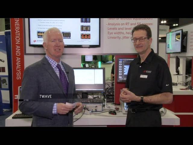
 How to test coherent digital signal processors by generating and analyzing transmission impairments
 -
 Keysight M8195A AWG The Digital and Arbitrary Signal Generator
 -
 Generating PAM-4 Signals using an M8195A Arbitrary Waveform Generator
 -
 Using a Keysight Arbitrary Waveform Generator M8195A for optical applications
 -
 Keysight M8195A AWG within the Mobile & Network Ecosystem


| General characteristics | |||||||
| M8195A | |||||||
| Sample rate | 53.76 GSa/s to 65.00 GSa/s or 26.88 GSa/s to 32.50 GSa/s (sample rate divider = 2) or 13.44 GSa/s to 16.25 GSa/s (sample rate divider = 4) | ||||||
| DAC resolution | 8 bits | ||||||
| Number of channels per M8195A module | 1, 2 or 4 (corresponds to Opt. 001, 002, 004) Number of channels is software upgradable via license key | ||||||
| Sample memory | |||||||
| M8195A | |||||||
| Internal sample memory | 1 MSa per module (for modes of operation see Sample memory modes table below) | ||||||
| Extended sample memory | 2 GSa per M8195A module (standard)16 GSa per M8195A module (with Option 16G) (for modes of operation see Sample memory modes table below) | ||||||
| Waveform granularity1 | |||||||
| Int. memory | 128 samples | ||||||
| Ext. memory, sample rate divider = 1 | 256 samples | ||||||
| Ext. memory, sample rate divider = 2 | 128 samples | ||||||
| Ext. memory, sample rate divider = 4 | 64 samples | ||||||
| Minimum waveform length | |||||||
| Int. memory | 128 samples | ||||||
| Ext. memory, sample rate divider = 1 | 1280 samples | ||||||
| Ext. memory, sample rate divider = 2 | 640 samples | ||||||
| Ext. memory, sample rate divider = 4 | 320 samples | ||||||
| Sample memory modes | |||||||
| Mode | Available with option | Sample memory (standard) | Sample memory (with Opt. 16G) | Max. sample rate | Interpolation1 | Max. output frequency2 | Analog BW (typ) (3 dB) |
| 1 ch, ext.mem. | 001, 002, 004 | 2 GSa | 16 GSa | 65 GSa/s | None | > 25 GHz | 25 GHz |
| 1 ch, int. mem. | 001, 002, 004 | 1 MSa | 1 MSa | 65 GSa/s | None | > 25 GHz | 25 GHz |
| 2 ch, ext.mem. | 002, 004 | 1 GSa per ch. | 8 GSa per ch. | 32.5 GSa/s | 2 x | 12.8 GHz | 25 GHz |
| 2 ch, int.mem. | 002, 004 | 512 KSa per ch. | 512 KSa per ch. | 65 GSa/s | None | > 25 GHz | 25 GHz |
| 4 ch, ext.mem. | 4 | 0.5 GSa per ch. | 4 GSa per ch. | 16.25 GSa/s | 4 x | 6.4 GHz | 25 GHz |
| 4 ch, int.mem. | 4 | 256 KSa per ch. | 256 KSa per ch. | 65 GSa/s | None | > 25 GHz | 25 GHz |
| Frequency switching characteristics | |||||||
| Effective frequency switching time3 | |||||||
| with Option FSW | 38 ps | ||||||
| without Option FSW | > 505 μs | ||||||
| Out 1, 2, 3, 4 | |||||||
| Output type | Single ended4 or differential | ||||||
| Bandwidth (3 dB, excl. sin(x)‚àïx roll-off) | 25 GHz (typ) | ||||||
| Rise/fall time5 (20% / 80%) | 18 ps (typ) | ||||||
| Impedance | 50 Ω (nom) | ||||||
| Amplitude | 75 mVpp to 1.0 Vpp, single-ended into 50 Ω 150 mVpp to 2.0 Vpp, differential | ||||||
| Amplitude resolution | 200 μV (nom) | ||||||
| DC amplitude accuracy6 | ±(2.5% +10 mV) (typ) | ||||||
| Voltage window | -1.0 V to +3.7 V single-ended into 50 Ω | ||||||
| Offset resolution | 200 μV (nom) | ||||||
| DC offset accuracy7 | ± 20 mV (typ) | ||||||
| Differential offset | In system adjustable to 0 mV | ||||||
| Termination voltage window | -1.0 V to + 3.7 V Vol ≤ 1.5 V: (low level - 500 mV) to (high level +1000 mV) Vol > 1.5 V: low level to (high level +1000 mV) | ||||||
| Total jitter, with pre-distortion | 6 ps (pp) at 32 Gb/s PRBS (nom) | ||||||
| Random jitter, RMS8 | 200 fs (typ) | ||||||
|
1. Interpolation is performed by FIR filters in hardware. For 2x (4x) interpolation, samples are read from memory at a rate up to 32.5 GSa/s (16.25 GSa/s) and interpolated to a DAC sample rate of up to 65 GSa/s. For interpolation = none, the sample rate from memory is the same as the DAC sample rate. 2. With default FIR configuration the maximum sample rate is calculated as 80% of Nyquist. With custom FIR configurations higher output frequencies can be achieved. 3. Effective switching frequency is determined as 1/fmax, with fmax = fSa(max) / 2.5 4. Unused output must be terminated with 50 Ω to GND. In case the termination voltage is not GND, the unused output must be terminated to VTerm. 5. Sample rate 64 GSa/s, output amplitude 500 mVpp(se). 6. Termination voltage = 0 V; adjusted at 23 °C ambient temperature, amplitude increases by 0.2%/°C (typ) for ambient temperature below 23 °C. 7. Termination voltage = 0 V. 8. 10 GHz clock; 1 V ampl.; 60 GSa/s. |
|||||||
| Harmonic distortions1’2 | |||||||
| 2nd harmonic |
-45 dBc (typ), fout < 3 GHz -35 dBc (typ), fout = 3 GHz... 6 GHz -30 dBc (typ), fout > 6 GHz |
||||||
| 3rd harmonic |
-45 dBc (typ), fout < 1 GHz -40 dBc (typ), fout = 1 GHz. 3 GHz -35 dBc (typ), fout = 3 GHz. 6 GHz -30 dBc (typ), fout > 6 GHz |
||||||
| Two-tone IMD1 | -45 dBc (typ), fout1 = 990 MHz, fout2 = 1010 MHz | ||||||
| SFDR1 (excluding harmonic distortions) | |||||||
| In-band |
-80 dBc (typ), fout = 100 MHz, measured DC to 1 GHz -70 dBc (typ), fout = DC…400 MHz, measured DC to 400 MHz -48 dBc (typ), fout = DC…4 GHz, measured DC to 4 GHz -53 dBc (typ), fout = 4 GHz…6 GHz, measured 4 GHz to 6 GHz -53 dBc (typ), fout = 6 GHz…8 GHz, measured 6 GHz to 8 GHz -50 dBc (typ), fout = 8 GHz…10 GHz, measured 8 GHz to 10 GHz -46 dBc (typ), fout = 10 GHz…12 GHz, measured 10 GHz to 12 GHz -50 dBc (typ), fout = 12 GHz…14 GHz, measured 12 GHz to 14 GHz -42 dBc (typ), fout = 14 GHz…16 GHz, measured 14 GHz to 16 GHz -42 dBc (typ), fout = 16 GHz…18 GHz, measured 16 GHz to 18 GHz -42 dBc (typ), fout = 18 GHz…20 GHz, measured 18 GHz to 20 GHz -48 dBc (typ), fout = 20 GHz…21 GHz, measured 20 GHz to 21 GHz -42 dBc (typ), fout = 21 GHz…22 GHz, measured 21 GHz to 22 GHz -40 dBc (typ), fout=22 GHz....24 GHz, measured 22 GHz to 24 GHz -40 dBc (typ), fout=24 GHz....26 GHz, measured 24 GHz to 26 GHz |
||||||
| Adjacent band |
-48 dBc (typ), fout = DC…4 GHz, measured DC to 8 GHz -48 dBc (typ), fout = 4 GHz…6 GHz, measured 3 GHz to 8 GHz -34 dBc (typ), fout = 6 GHz…8 GHz, measured 4 GHz to 10 GHz -34 dBc (typ), fout = 8 GHz…10 GHz, measured 6 GHz to 12 GHz -46 dBc (typ), fout = 10 GHz…12 GHz, measured 8 GHz to 14 GHz -42 dBc (typ), fout = 12 GHz…14 GHz, measured 10 GHz to 16 GHz -32 dBc (typ), fout = 14 GHz…16 GHz, measured 12 GHz to 18 GHz -30 dBc (typ), fout = 16 GHz…18 GHz, measured 14 GHz to 20 GHz -40 dBc (typ), fout = 18 GHz…20 GHz, measured 16 GHz to 22 GHz -35 dBc (typ), fout=20 GHz....22 GHz, measured 18 GHz to 24 GHz -30 dBc (typ), fout=22 GHz....24 GHz, measured 20 GHz to 26 GHz -28 dBc (typ), fout=24 GHz....25 GHz, measured 22 GHz to 27 GHz -28 dBc (typ), fout=25 GHz....26 GHz, measured 23 GHz to 27 GHz |
||||||
| Amplitude flatness (at SMA connector,3 compensated for sin(x)‚àïx) |
±2 dB (typ), fout= DC…10 GHz +2 dB, -3 dB (typ), fout = 10…25 GHz (typ) |
||||||
| Connector type | 2.92 mm “K-style” (female) | ||||||
|
1. Sample rate 64 GSa/s, output amplitude 500 mVpp(se). 2. Measured with a balun (e.g. HL 9405). 3. Measured at Data Out. |
|||||||
| Run modes | |||||||
| Continuous | |||||||
| Int. Memory | A waveform segment is continuously repeated | ||||||
| Ext. Memory | A waveform segment/sequence/scenario is continuously repeated | ||||||
| Triggered | |||||||
| Int. Memory | A waveform segment is looped continuously after a trigger event is received | ||||||
| Ext. Memory | A waveform segment/sequence/scenario is generated once after a trigger event is received | ||||||
| Gated | |||||||
| Int. Memory | A waveform segment is looped continuously after a rising edge of the trigger/gate input | ||||||
| Ext. Memory | A waveform segment/sequence/scenario is generated as long as the trigger/gate input is high | ||||||
| Sequencer modes | |||||||
| The sample memory can be split into a maximum of 16 M waveform segments. Waveform segments can have different sizes, but the segment size must be the same across channels. The sequence table can contain up to 16 M entries (sequence IDs). | |||||||
| Arbitrary | |||||||
| Int. Memory | One waveform segment of arbitrary length is continuously looped | ||||||
| Ext. Memory | |||||||
| Sequence (requires Opt. SEQ) | |||||||
| Int. Memory | Not available | ||||||
| Ext. Memory | One or more waveform segments are arranged in a linear sequence. Each segment can be repeated a programmable number of times or until an external event is signaled. | ||||||
| Scenario (requires Opt. SEQ) | |||||||
| Int. Memory | Not available | ||||||
| Ext. Memory | One or more sequences are arranged in a linear sequence. Each sequence can be repeated a programmable number of times or until an external event is signaled | ||||||
| Trigger/gate input | |||||||
| Input range | -4 V to +4 V | ||||||
| Threshold | |||||||
| Range | -4 V to +4 V | ||||||
| Resolution | 10 mV (nom) | ||||||
| Sensitivity | 100 mV (typ) | ||||||
| Polarity | Selectable, positive or negative | ||||||
| Input impedance | 50 Ω (nom), DC coupled | ||||||
| Connector type | SMA (female) | ||||||
| Trigger/gate input | |||||||
| A trigger/gate input is provided on the front panel of the M8195A and the M8197A. The trigger input is used to start/gate waveform playback. | |||||||
| The trigger/gate input of the M8195A affects the channels of that M8195A. - | |||||||
| Input range | -4 V to +4 V | ||||||
| Threshold | |||||||
| Range | -4 V to +4 V | ||||||
| Resolution | 10 mV (nom) | ||||||
| Sensitivity | 100 mV (typ) | ||||||
| Polarity | Selectable, positive or negative | ||||||
| Input impedance | 50 Ω (nom), DC coupled | ||||||
| Max. toggle rate1 | |||||||
| Sample rate divider = 1 | Sample rate/3584 | ||||||
| Sample rate divider = 2 | Sample rate/1792 | ||||||
| Sample rate divider = 4 | Sample rate/896 | ||||||
| Connector type | SMA (female) | ||||||
| Trigger output (M8195A only) | |||||||
| The “Trigger output” and “Event input” functions share the same connector on the front panel. The “Trigger output” functionality is only used in conjunction with the 81195A Optical Modulation Generator Software. For details of using the “Trigger output” functionality, refer to the 81195A data sheet und user guide. | |||||||
| Output impedance | M8195A | ||||||
| 50 Ω (nom) | |||||||
| Level | |||||||
| Voltage window | -0.5 V to 2.0 V | ||||||
| Amplitude | 200 mVpp to 2.5 Vpp | ||||||
| Resolution | 10 mV | ||||||
| Accuracy | ± (10% + 25 mV) (typ) | ||||||
| Rise/fall time (20% to 80%) | 150 ps (nom) | ||||||
| Width | 20ns (1280 sample clock cycles @ 64GS‚àïs) | ||||||
| Timing characteristics | |||||||
| The sequencing of a single M8195A can be controlled with the ‘Trigger/Gate Input' as well as the ‘Event Input' of the M8195A. In a synchronous system that consists of one M8197A and up to four M8195A, the sequencing of the entire synchronous system can be controlled with the ‘Trigger/Gate Input' as well as the ‘Event Input' of the M8197A. A single M8195A or a synchronous system can operate asynchronously or synchronously. In case of synchronous operation, a timing requirement between the Reference Clock Output and ‘Trigger/Gate Input' or ‘Event Input' must be met. | |||||||
| Delay | M8195A | ||||||
| Trigger/Gate Input to Data Out | 40192 sample clock cycles + 0 ns (nom) | ||||||
| Event Input to Data Out | 40192 sample clock cycles + 0.15 ns (nom) | ||||||
| Delay accuracy, asynchronous operation | |||||||
| Trigger/Gate Input to Data Out | ± 100 ps (typ) | ||||||
| Event Input to Data Out | ± 100 ps (typ) | ||||||
| Delay accuracy, synchronous operation | |||||||
| Trigger/Gate Input to Data Out | ± 1 ps (typ) | ||||||
| Event Input to Data Out | ± 1 ps (typ) | ||||||
| Synchronous operation | |||||||
| Set-up time | -2.5 ns (typ) (‘TRIG IN', ‘EVENT IN' to rising edge of ‘REF CLK OUT') | ||||||
| Hold time | 5.1 ns (typ) (Rising edge of ‘REF CLK OUT' to ‘TRIG IN', ‘EVENT IN') | ||||||
| Skew between normal and complement | 0 ps ± 1 ps (nom) | ||||||
| Skew between any pair of outputs | |||||||
| within one M8195A module | 0 ps ± 5 ps (typ) 1 | ||||||
| across multiple M8195A modules | 0 ps ± 100 ps (typ) 2 | ||||||
| Variable channel delay | |||||||
|
In order to compensate for external cable length differences as well as the initial skew, channels 1, 2, 3 and 4 can be individually delayed with a very high timing resolution. There are two possibilities to adjust the variable channel delay: –– The sample clock delay can be changed in discrete steps. The step size is 1 / DAC Sample Frequency. E.g. the step size is 15.625 ps for a DAC Sample Frequency of 64 GHz. –– The FIR delay can be used for sub sample delay adjust. Note: This delay functionality uses a digitally implemented FIR filter with limited length and accuracy. As a result the output signal may show some degradation when using the FIR delay adjust. |
|||||||
| Sample clock delay range | 0 ... 95 sample clocks | ||||||
| FIR delay range | |||||||
| Sample Rate Divider = 1 | -50 ps...+50 ps | ||||||
| Sample Rate Divider = 2 | -100 ps...+100 ps | ||||||
| Sample Rate Divider = 4 | -200 ps.+200 ps | ||||||
| FIR delay resolution | 10 fs | ||||||
| Variable module delay | |||||||
| In order to compensate for external cable length differences as well as the initial skew, channels 1,2, 3 and 4 can be jointly delayed with a very high timing resolution. In case the M8197A synchronization module is used to configure a synchronous system, the variable delay can be used to align the channels of multiple M8195A modules. Modifying the variable delay always affects the delay of all four channels. E.g. setting the variable delay to 10 ps has the following effect. Out 1, 2, 3 and 4 are delayed by 10 ps with respect to trigger/gate input and event input. | |||||||
| Delay range | 0 ns to 10 ns | ||||||
| Delay resolution | 50 fs | ||||||
| Delay accuracy | ± 10 ps (typ) | ||||||
| FIR filter | |||||||
| Each channel in the M8195A has an FIR filter with programmable coefficients in front of its respective DAC. The FIR filters are used to realize variable channel delay and waveform interpolation with sample rate divider 2 and 4. The following presets are available for the FIR filter coefficients: Nyquist, Low Pass, Linear Interpolation, Zero Order Hold and User Defined. The number of taps of each filter is 16 when internal memory is used and depends on the sample rate divider when extended memory is used as shown in the following table: | |||||||
| Sample Rate Divider | Taps | Memory Sample Rate | DAC Sample Rate | ||||
| 1 | 16 | 53.76 GSa/s ... 65.00 GSa/s | 53.76 GSa/s . 65.00 GSa/s | ||||
| 2 | 32 | 26.88 GSa/s . 32.50 GSa/s | 53.76 GSa/s . 65.00 GSa/s | ||||
| 3 | 64 | 13.44 GSa/s . 16.25 GSa/s | 53.76 GSa/s . 65.00 GSa/s | ||||
| Reference clock input | |||||||
| The clock reference input is provided on the front panel of each module. The clock reference input of the M8195A is used as the clock reference for all four channels of that M8195A. The clock reference input of the M8197A synchronization module is used as the clock reference for all channels of all M8195A that are combined in a synchronous system. | |||||||
| Input frequency ranges | 10 MHz to 300 MHz 210 MHz to 17 GHz | ||||||
| Lock range | ± 1% (typ) | ||||||
| Jitter | < 2 pspp | ||||||
| Input level 10 MHz - 10 GHz 10 GHz - 17 GHz | 250 mVpp to 2 Vpp 500 mVpp to 2 Vpp | ||||||
| Impedance | 50 Ω (nom), AC coupled | ||||||
| Connector | SMA | ||||||
| Sample clock frequency resolution | 1 ppm; e.g. sample clock frequency = 64 GHz => frequency resolution = 64 kHz | ||||||
| Reference clock output | |||||||
| The clock reference output is provided on the front panel of each module. | |||||||
| AXIe backplane clock source | |||||||
| Output frequency |
fOut1 = fSa / (32 * n) with n = 1...1024 or fOut2 = fSa / 256 |
||||||
| Frequency accuracy | ± 20 ppm | ||||||
| Internal clock source | |||||||
| Output frequency |
fOut1 = fSa / (32 * n) with n = 1.1024 or fOut2 = fSa / 256 or fOut2 = 100 MHz |
||||||
| Frequency accuracy | See internal synthesizer clock characteristic | ||||||
| External reference clock input frequency fIn = 10 MHz to 300 MHz | |||||||
| Output frequency | fOut2 = fIn / (n * m) with n, m = 1.8 or | ||||||
| fOut2 = fSa / 256 | |||||||
| Frequency accuracy | Depends on external reference clock | ||||||
| External reference clock input frequency fIn = 210 MHz to 17 GHz | |||||||
| Output frequency | fOut1 = fSa / (32 * n) with n = 1.1024 or | ||||||
| fOut2 = fSa / 256 | |||||||
| Frequency accuracy | Depends on external reference clock | ||||||
| Output amplitude | 900 mVpp (nom) into 50 Ω | ||||||
| Source impedance | 50 Ω (nom), AC coupled | ||||||
| Connector | SMA | ||||||
|
1. Reference clock output phase shifts when the variable delay is changed. 2. For M8195A: Reference clock output remains unchanged when the variable delay is changed. 3. Warm-up time 2 minutes min. 4. fSa = 64 GHz; reference clock source: internal. |
|||||||
| Internal synthesizer clock characteristics | |||||||
| Frequency | 53.76 GHz to 65.00 GHz | ||||||
| Accuracy1 | 0.7 ppm (spec) initial accuracy | ||||||
| ± 0.3 ppm aging / year | |||||||
| Frequency resolution | 7 digits, e.g. 100 Hz at 1 GHz | ||||||
| Phase noise2 | < -115 dBc/Hz (typ) at 10 kHz offset, fOUT = 1 GHz | ||||||
| < -95 dBc/Hz (typ) at 10 kHz offset, fOUT = 10 GHz | |||||||
| Download speed | |||||||
| Download speed is measured by transferring the samples from the controlling PC's memory into the M8195A. | |||||||
| USB using SCPI or IVI | PCIe using SCPI3 | PCIe using IVI3,4 | |||||
| Download Speed | ~8 MSa/s (meas) | ~40 MSa/s (meas) | ~400 MSa/s (meas) | ||||
| Instrument software | |||||||
| The M8195A and M8197A are controlled by a combined soft-front panel and firmware application that runs on an embedded AXIe controller or external PC or laptop. | |||||||
| Supported Operating Systems | Windows 7 (32 or 64 bit), Windows 8 / 8.1 (32 or 64 bit), Windows 10 (32 or 64 bit) | ||||||
| Required hard disk space | 1 Gb | ||||||
| Interface to hardware | PCI Express® or USB | ||||||
| Application programming interfaces | SCPI, IVI-COM, LabView | ||||||
| General | |||||||
| Power consumption | 180 W (nom) @ 65 GSa/s | ||||||
| Operating temperature | 0 °C to 40 °C | ||||||
| Operating humidity | 5% to 80% relative humidity, non-condensing | ||||||
| Operating altitude | Up to 2000 m | ||||||
| Storage temperature | -40 °C to +70 ° | ||||||
| Stored states | User configurations and factory default | ||||||
| Interface to controlling PC | PCIe (see AXIe chassis specification) or USB | ||||||
| Form factor | 1-slot AXIe | ||||||
| Dimensions (W x H x D) | 322.25 mm x 30 mm x 281.5 mm | ||||||
| Weight | 3.75 kg | ||||||
| Safety designed to | IEC61010-1, UL61010, CSA22.2 61010.1 tested | ||||||
| EMC tested to | IEC61326-1 | ||||||
| Warm-up time | 30 min | ||||||
| Calibration interval | 2 years recommended | ||||||
| Cooling requirements | When operating the system choose a location that provides at least 80 mm of clearance at rear, and at least 30 mm of clearance at each side | ||||||
|
1. Warm-up time 2 minutes min. 2. fSa = 64 GHz; reference clock source: internal. 3. Using M9048A PCIe adapter. 4. Download of waveform samples without marker information. |
|||||||
| Definitions | |||||||
| Specification (spec) | |||||||
| The warranted performance of a calibrated instrument that has been stored for a minimum of 2 hours within the operating temperature range of 0°C to 40°C and after a 45-minute warm up period. All specifications include measurement uncertainty and were created in compliance with ISO-17025 methods. Data published in this document are specifications (spec) only where specifically indicated. | |||||||
| Typical (typ) | |||||||
| The characteristic performance, which 80% or more of manufactured instruments will meet. This data is not warranted, does not include measurement uncertainty, and is valid only at room temperature (approximately 23°C). | |||||||
| Nominal (nom) | |||||||
| The mean or average characteristic performance, or the value of an attribute that is determined by design such as a connector type, physical dimension, or operating speed. This data is not warranted and is measured at room temperature (approximately 23°C). | |||||||
| Measured (meas) | |||||||
| An attribute measured during development for purposes of communicating the expected performance. This data is not warranted and is measured at room temperature (approximately 23°C). | |||||||
| Accuracy | |||||||
| Represents the traceable accuracy of a specified parameter. Includes measurement error and timebase error, and calibration source uncertainty. | |||||||
–¢–æ–≤–∞—Ä |
|
|
|
–ú–æ–¥–µ–ª–∏ –∏ –û–ø—Ü–∏–∏ |
–û–ø–∏—Å–∞–Ω–∏–µ |
–¶–µ–Ω–∞ | –ó–∞–∫–∞–∑–∞—Ç—å |
0
| –ú–æ–¥–µ–ª–∏ |
|
M8195A
|
–ì–µ–Ω–µ—Ä–∞—Ç–æ—Ä —Å–∏–≥–Ω–∞–ª–æ–≤ –ø—Ä–æ–∏–∑–≤–æ–ª—å–Ω–æ–π —Ñ–æ—Ä–º—ã, 65 –ì–≤—ã–±./—Å
|
–ü–æ –∑–∞–ø—Ä–æ—Å—É |
1
| –ì–∞—Ä–∞–Ω—Ç–∏—è, –∫–∞–ª–∏–±—Ä–æ–≤–∫–∞, —Å–µ—Ä–≤–∏—Å–Ω–æ–µ –æ–±—Å–ª—É–∂–∏–≤–∞–Ω–∏–µ |
|
R-50C-011-3
|
Calibration Assurance Plan - Return to Keysight - 3 years
|
–ü–æ –∑–∞–ø—Ä–æ—Å—É | ||
|
R-50C-011-5
|
Calibration Assurance Plan - Return to Keysight - 5 years
|
–ü–æ –∑–∞–ø—Ä–æ—Å—É | ||
|
R-51B-001-3C
|
Warranty Assurance Plan - Return to Keysight - 3 years
|
–ü–æ –∑–∞–ø—Ä–æ—Å—É | ||
|
R-51B-001-5C
|
Warranty Assurance Plan - Return to Keysight - 5 years
|
–ü–æ –∑–∞–ø—Ä–æ—Å—É |
5
| –û–ø—Ü–∏–∏ –∏ –∞–∫—Å–µ—Å—Å—É–∞—Ä—ã |
|
M8195A-BU3
|
Bundle consisting of one M9502A 2-slot AXIe Chassis with USB Option and one M9537A AXIe Embedded PC Controller
|
–ü–æ –∑–∞–ø—Ä–æ—Å—É | ||
|
M8195A-FSW
|
Fast Switching
|
–ü–æ –∑–∞–ø—Ä–æ—Å—É | ||
|
M8195A-SCD
|
Standard Calibration Document
|
–ü–æ –∑–∞–ø—Ä–æ—Å—É | ||
|
M8195A-SEQ
|
Sequencer
|
–ü–æ –∑–∞–ø—Ä–æ—Å—É | ||
|
M8195A-U12
|
Arbitrary Waveform Generator Upgrade of M8195A-R12 or -E52 to Revision 2
|
–ü–æ –∑–∞–ø—Ä–æ—Å—É | ||
|
M8195A-U14
|
Arbitrary Waveform Generator Upgrade of M8195A-R14 or -E54 to Revision 2
|
–ü–æ –∑–∞–ø—Ä–æ—Å—É | ||
|
M8195A-Z54
|
Calibration Certificate for Z540
|
–ü–æ –∑–∞–ø—Ä–æ—Å—É | ||
|
81195A-OSP
|
Optical Signal Properties, transportable, perpetual License
|
–ü–æ –∑–∞–ø—Ä–æ—Å—É | ||
|
81195A-RSP
|
Real-time Signal Processing, transportable, perpetual License
|
–ü–æ –∑–∞–ø—Ä–æ—Å—É | ||
|
M8070A-0NP
|
System Software for M8000 Series of BER Test Solutions, Network/Floating, Perpetual License
|
–ü–æ –∑–∞–ø—Ä–æ—Å—É | ||
|
M8195A-001
|
Arbitrary Waveform Generator, 1 Channel, 65 GSa/s
|
–ü–æ –∑–∞–ø—Ä–æ—Å—É | ||
|
M8070A-0TP
|
System Software for M8000 Series of BER Test Solutions, Transportable, Perpetual License
|
–ü–æ –∑–∞–ø—Ä–æ—Å—É | ||
|
M8070A-1NP
|
DUT Control Interface, Network/Floating, Perpetual License
|
–ü–æ –∑–∞–ø—Ä–æ—Å—É | ||
|
M8070A-1TP
|
DUT Control Interface, Transportable, Perpetual License
|
–ü–æ –∑–∞–ø—Ä–æ—Å—É | ||
|
N6171A
|
MATLAB Software
|
–ü–æ –∑–∞–ø—Ä–æ—Å—É | ||
|
N6171A-M01
|
MATLAB-Basic Package, individual license - node-locked
|
–ü–æ –∑–∞–ø—Ä–æ—Å—É | ||
|
N6171A-M02
|
MATLAB-Standard Package, individual license - node-locked
|
–ü–æ –∑–∞–ø—Ä–æ—Å—É | ||
|
N6171A-M03
|
MATLAB-Advanced Package, individual license - node-locked
|
–ü–æ –∑–∞–ø—Ä–æ—Å—É | ||
|
Y1202A
|
PCIe cable: x8, 2.0m
|
–ü–æ –∑–∞–ø—Ä–æ—Å—É | ||
|
M8195A-002
|
Arbitrary Waveform Generator, 2 Channels, 65 GSa/s
|
–ü–æ –∑–∞–ø—Ä–æ—Å—É | ||
|
M8195A-004
|
Arbitrary Waveform Generator, 4 Channels, 65 GSa/s
|
–ü–æ –∑–∞–ø—Ä–æ—Å—É | ||
|
M8195A-16G
|
Upgrade to 16 GSa Memory
|
–ü–æ –∑–∞–ø—Ä–æ—Å—É | ||
|
M8195A-1A7
|
Calibration + Uncertainties + Guardbanding (Not Accredited)
|
–ü–æ –∑–∞–ø—Ä–æ—Å—É | ||
|
M8195A-810
|
Matched Cable Pair for M8195A AWG, 2.92 mm
|
–ü–æ –∑–∞–ø—Ä–æ—Å—É | ||
|
M8195A-BU1
|
Bundle consisting of one M9505A 5-slot AXIe Chassis with USB Option and one M9537A AXIe Embedded PC Controller
|
–ü–æ –∑–∞–ø—Ä–æ—Å—É | ||
|
M8195A-BU2
|
Bundle consisting of one M9502A 2-slot AXIe Chassis with USB Option
|
–ü–æ –∑–∞–ø—Ä–æ—Å—É |
